If you have ever pulled a plug-in board out of a 19-inch subrack, you have probably seen the connectors mounted at the rear of the chassis. Those connectors are usually connected to a backplane.
In simple terms, a backplane is the board at the rear of a subrack that provides the connection between the plug-in PCBs and the rest of the system.
It sounds simple, but the backplane is one of the parts that can cause problems when an older subrack needs to be repaired or modified. A replacement backplane has to match the PCB position, connector arrangement, mounting holes, board pitch, and sometimes the existing wiring or system architecture.
That is why replacing one is not always as easy as finding a PCB with the same overall size.
How Does a Backplane Work in a 19-Inch Subrack?
A typical Eurocard-style subrack has several PCBs installed vertically. Each board slides into a pair of guide rails from the front of the chassis.
When the board reaches the rear of the subrack, its connector mates with a connector mounted on the backplane.
The basic arrangement is:
PCB → Backplane Connector → Backplane → System
The backplane can connect several boards together or provide connections from the plug-in boards to external equipment.
For example, a controller board, I/O board, communication board, and power-related board may all plug into the same backplane. Instead of running separate cables between every board, the backplane provides a fixed connection point.
This is one of the reasons modular subrack systems are still useful in industrial equipment. A board can be removed for maintenance without having to disconnect a large number of individual wires.
Where Is the Backplane Installed?
The backplane is normally located at the rear of the subrack.
From the front, you see the PCBs, front panels, handles, and guide rails. From the rear, you may see the backplane itself, rear I/O connectors, or other connections depending on the design.
The exact mechanical arrangement varies from one system to another.
A simple Eurocard subrack might have a backplane with one connector for each card position. A more complicated system may have several connector types, rear I/O connections, power connections, or a custom layout.
This is worth keeping in mind when looking for a replacement. Two backplanes can have the same 3U or 6U height and still be completely different parts.
Backplane vs. Backplane Connector
These two terms are often mixed together, but they refer to different things.
The backplane is the board or assembly installed at the rear of the subrack.
The backplane connector is the connector mounted on it. The connector mates with the corresponding connector on the plug-in PCB.
DIN 41612 connectors, covered by the IEC 60603-2 connector family, are commonly found in Eurocard-based systems.
For an existing machine, you may therefore need to identify both the backplane and the connector.
This becomes particularly important with older equipment. A connector may look almost identical to another model but have a different contact arrangement, mounting style, or mating configuration.
If you are replacing an existing part, the original part number or a clear photograph is often a much better starting point than simply searching for “Eurocard connector.”
Why Is Backplane Alignment So Important?
This is where the mechanical side of the design becomes important.
Suppose the PCB slides smoothly through the guide rails but the connector does not mate properly with the backplane. The problem may not actually be the connector.
The backplane could be mounted at the wrong position. The guide rail could be at the wrong height. The PCB pitch could be different. Or the connector itself could have a different mounting dimension.
Even a small difference can make a noticeable difference when several connectors have to mate at the same time.
For this reason, the backplane, guide rails, PCB and connectors should be considered as one mechanical system.
This is especially important for replacement parts. A backplane that works electrically may still be unusable if the PCB cannot line up with the connector.
3U and 6U Backplanes
You will often see backplanes described as 3U or 6U.
These terms refer to the height of the subrack system and the corresponding plug-in board format.
3U systems are commonly used where a relatively compact board format is sufficient. 6U systems provide more board height and are widely used in applications such as VME and other larger modular systems.
But “3U backplane” or “6U backplane” is only a starting point when specifying a replacement.
You still need to check things such as:
- Number of card positions
- PCB pitch
- Connector type
- Connector position
- Mounting-hole pattern
- PCB dimensions
- Rear I/O arrangement
- Mechanical clearance
This is why simply searching for a “3U backplane” may not lead to the right replacement.
Backplanes in Eurocard, VME and CompactPCI Systems
Backplanes are closely associated with modular architectures such as Eurocard, VME and CompactPCI.
The mechanical format may look similar from the outside, but the electrical and connector arrangements can be very different.
For example, a VME system may use a particular connector arrangement and backplane architecture, while another Eurocard-based industrial system may use a completely different configuration.
When identifying an existing backplane, it is therefore useful to know more than just the name of the system.
The following information can help:
- System type
- Board size
- Number of slots
- Connector type
- Connector arrangement
- Board pitch
- Backplane dimensions
If the original drawing is available, even better.
When Do You Need to Replace a Backplane?
Backplanes are usually replaced for one of three reasons: repair, obsolescence, or system modification.
A damaged connector or PCB can make an existing system difficult to maintain. In older equipment, the original backplane may no longer be available from the original manufacturer.
Another common situation is an equipment upgrade. The enclosure and basic mechanical structure may still be perfectly usable, but the customer wants to change the PCB arrangement or add new I/O connections.
In these cases, a replacement or custom backplane can sometimes extend the life of the existing equipment without redesigning the entire subrack.
For maintenance departments, this can be more practical than replacing a complete chassis.
What Should You Send to a Supplier?
If you need a replacement backplane, don’t worry if you don’t have a complete engineering drawing.
Start with whatever information you have.
A supplier can usually make a much better assessment if you can provide:
Original part number
Photos of the backplane
Overall dimensions
Number of slots
PCB dimensions
Connector part number or photos
Mounting-hole dimensions
Board pitch
Existing drawings or PCB files
A photo of the complete backplane plus a close-up of the connector is often surprisingly useful for the first evaluation.
If the original part is no longer available, the supplier may be able to work from a sample, drawing, or measurements and develop a replacement.
Standard Backplane or Custom Backplane?
There is no single backplane that fits every 19-inch subrack.
If your equipment follows a well-established architecture, a standard backplane may be the simplest option.
Older industrial equipment is often a different story. The backplane may have been designed specifically for that machine, with a non-standard connector layout or mounting pattern.
In that situation, a custom backplane may be the more practical solution.
The same applies when you want to keep the existing subrack but change the PCB arrangement, add connectors, or replace an obsolete interface.
For these projects, mechanical drawings and connector information are usually more valuable than simply specifying “19-inch backplane.”
The Backplane Is Only One Part of the System
When working on an existing subrack, it is easy to focus on the backplane and overlook the parts around it.
But the PCB still needs to slide through the guide rails. The front panel needs to sit correctly on the card. The connector needs to reach the correct position. The backplane needs to be securely fixed to the chassis.
So a backplane replacement may involve several related components:
- Backplane
- DIN 41612 / Eurocard connectors
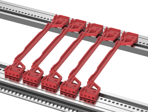
- PCB guide rails
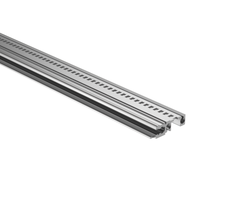
- Horizontal rails
- Front panels
- PCB handles
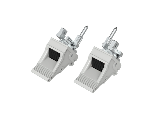
- Mounting hardware
Checking these interfaces together can save a lot of time during installation.
Looking for a Replacement Backplane or Connector?
If you are repairing an existing 19-inch subrack and cannot find the original backplane or connector, send us what you have.
A part number, drawing, dimensions, PCB layout, or even clear photos can be enough for us to start checking the design.
We can help with replacement and custom components for 19-inch subracks, Eurocard systems and related electronic equipment, including backplane connectors, PCB guide rails, front panels, horizontal rails and other mechanical parts.
Send us the original part information and let us check the compatibility with you.