A practical selection guide for procurement engineers and hardware designers
If you are sourcing or specifying a DIN 41612 connector for a Eurocard backplane, this guide gives you a decision sequence you can work through in order — from system architecture down to the exact part number — plus the checkpoints that prevent the most common purchasing and design mistakes.
DIN 41612 (IEC 60603-2) remains the default two-piece connector for VMEbus, NuBus, and many legacy or industrial backplanes. Its 2.54 mm grid guarantees mechanical interchangeability across brands — but only if you specify the right Type, Class, and termination.
Quick Selection Flow
| Decision | Question to Answer | Typical Answer |
|---|---|---|
| Type | How many rows / pins / current per contact? | Type C (96-pin signal), Type R (reversed C), Type D/E (power), Type M (hybrid) |
| Contacts | How many signals + power lines? | 16 / 32 / 48 / 64 / 96, with selective loading allowed |
| Class | How many mating cycles? Corrosive environment? | Class 2 for industrial, Class 1 for harsh/high-reliability |
| Termination | Backplane or daughter card? Which soldering process? | Press-Fit for backplane, Through-Hole for daughter card |
| Orientation | Normal or Reversed? | Confirm against existing mating half |
Step 1: Lock the Type — It Determines Rows, Pins, and Current
The letter code is the first thing to fix, because it constrains everything downstream.
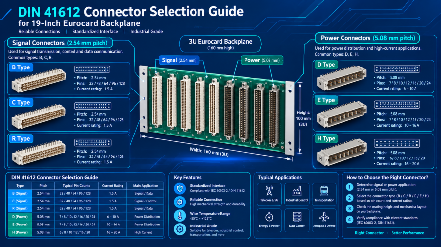
Type C — the workhorse. Three rows (a/b/c), up to 96 contacts, 2.54 mm pitch. Default for VMEbus and most Eurocard signal backplanes.
Type B — two rows, up to 64 contacts. Use when pin count is low and board space is tight.
Type R — the reversed Type C. Female socket with right-angle pins mounts on the backplane; male header with straight pins mounts on the daughter card. Choose this when your architecture requires a male header on the backplane side.
Type D / Type E — power and high-voltage. 5.08 mm pitch, fewer contacts, larger creepage distance. Type D: up to 32 contacts (2 rows). Type E: up to 48 contacts (3 rows). Roughly 6 A per contact.
Type F / Type H — higher current. Type H reaches about 15 A per contact but with far fewer positions (e.g., H15 = 15 contacts).
Type M — hybrid. Mixes signal, coaxial, high-current, and even fiber optic contacts in one housing. Best for custom backplanes carrying multiple signal types through a single connector.
Procurement note: Type C and Type R are electrically similar but mechanically opposite. Never substitute one for the other without confirming the mating half.
Step 2: Confirm Contact Count and Loading
Contact count is set by rows × columns: two-row connectors use rows a+b or a+c; three-row use a+b+c; 16 or 32 columns per row. Standard counts: 16, 32, 48, 64, 96.
Selective loading lets you buy a 96-position housing and populate only the contacts you need — lower cost, less crosstalk between adjacent pins. Caveat: empty positions change parasitic parameters, so re-verify signal integrity for high-speed nets.
Step 3: Choose the Performance Class
DIN 41612 defines three classes based on gold plating thickness and mating cycles:
| Class | Mating Cycles | Typical Application |
|---|---|---|
| Class 1 | 500 | Military, aerospace, high-reliability |
| Class 2 | 400 | Industrial — the mainstream choice |
| Class 3 | 50 | Field-installed once, rarely re-mated |
Do not select on mating cycles alone. In salt spray, sulfide, or high-humidity environments, Class 1 vs. Class 2 matters more for contact resistance stability after corrosion exposure. For chemical, mining, or marine deployments, specify Class 2 minimum even if mating cycles are low.
Step 4: Match the Termination to Your Backplane Process
| Termination | Best For | Key Considerations |
|---|---|---|
| Press-Fit | Backplane female sockets | Gas-tight cold weld, no solder, reworkable. Requires good plated-hole quality and insertion-force calculation. |
| Through-Hole | Daughter card male headers | Confirm wave / selective / pin-in-paste reflow. Plastic housing temperature rating must match the process (LCP for reflow; PBT may not survive). |
| Wire-Wrap | Legacy maintenance only | Rarely used in new designs. |
Process note: If your backplane is thick and multilayers, press-fit avoids the thermal stress of wave soldering and is usually the safer choice.
Step 5: Watch for Reversed Versions and Pin Numbering
This is the classic trap when replacing connectors:
- Normal: male right-angle header on daughter card, female straight socket on backplane.
- Reversed: the opposite.
Pin numbering guarantees “a1 is always a1,” but when you replace a Normal female socket with a Reversed one, male a1 mates with female a32 — row order unchanged, column order mirrored. Board-to-board direct mating (no backplane) is especially vulnerable. Always confirm Normal/Reversed during schematic review and before releasing a PO.
Procurement & Compatibility Checklist
Verify these against the datasheet before finalizing your BOM:
- Pitch — 2.54 mm or 5.08 mm; row spacing matches footprint
- Plating — gold thickness ≥ 0.76 µm (30 µin) for the 500-cycle class
- Flame rating — UL 94 V-0 minimum
- Operating temperature — typically −55°C to +125°C
- EMLB (early-mate/late-break) — confirm extended pins if hot-swap is required
- Mating pair — DIN 41612 is a two-piece system; confirm male/female model correspondence
- Normal vs. Reversed — confirmed against the existing mating half
- Selective loading — confirmed with supplier if not fully populated
Bottom Line for Buyers and Engineers
Three decisions cover about 80% of DIN 41612 selection scenarios:
- Type — Type C or Type R for the vast majority of signal applications.
- Class — Class 2 or above for industrial and harsh environments.
- Termination — Press-Fit for backplanes, Through-Hole for daughter cards.
Lock those three, then verify the checklist above. For VMEbus and custom Eurocard backplanes, www.subrackparts.com stocks matching DIN 41612 connectors, backplanes, and subrack hardware — confirm your Type, Class, and Normal/Reversed orientation with our team before ordering to avoid mating mismatches.