When designing or repairing a 19-inch subrack, the PCB guide rail may look like a small mechanical component, but it plays an important role in PCB positioning, insertion, connector alignment, and mechanical stability.
For engineers and equipment manufacturers, choosing the correct PCB guide rail mounting type is especially important when building Eurocard systems, CompactPCI systems, industrial control equipment, railway electronics, and automated test systems.
The most common mounting methods include snap-in mounting, screw-mounted installation, and combined snap-in/screw fastening.
This guide explains the differences between these mounting types and how to choose the right PCB guide rail for your 19-inch subrack.
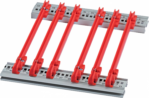
A PCB guide rail, also called a PCB card guide or card guide rail, is installed inside a subrack to guide and support a printed circuit board during insertion and removal.
Its main functions include:
- Guiding the PCB into the correct position
- Supporting the PCB edge
- Preventing excessive lateral movement
- Protecting the PCB edge from mechanical damage
- Helping maintain alignment with the backplane connector
- Supporting reliable insertion and removal
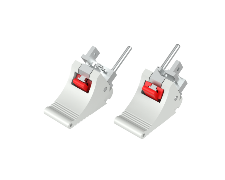
- Providing optional ESD or grounding functions
In a typical 19-inch subrack, the guide rail works together with the horizontal rail, front panel, PCB extractor, and backplane.
For this reason, selecting a guide rail only by its length is not sufficient.
You should also consider the mounting method, PCB thickness, guide groove width, rail height, PCB depth, and subrack structure.
3 Common PCB Guide Rail Mounting Types
For 19-inch subrack applications, three mounting configurations are particularly common:
- Snap-in PCB guide rails
- Screw-mounted PCB guide rails
- Snap-in + screw fastening guide rails
Each design has different advantages depending on the application.1. Snap-In PCB Guide Rails
The snap-in guide rail is designed to be installed by pressing the guide rail into a corresponding slot, hole, or mounting feature on the subrack support rail.
No separate screw is normally required for the primary installation.
Advantages of Snap-In Guide Rails
The biggest advantage is installation speed.
A technician can install or replace a guide rail without using additional screws or tools. This makes snap-in designs particularly useful when many guide rails need to be installed in a high-density card cage.
Typical advantages include:
- Fast installation
- Tool-free assembly
- Easy replacement
- Lower assembly cost
- Suitable for high-volume production
- Easy adjustment during initial assembly
Snap-in card guides are widely used where the mechanical structure provides a suitable mounting interface. Some commercial subrack systems specifically offer snap-in guide rails as an alternative to screw fastening.
When Should You Choose Snap-In Guide Rails?
Snap-in mounting is a good option when:
- The subrack has compatible mounting holes or slots
- Fast assembly is important
- The equipment is not exposed to extreme mechanical loads
- Guide rail replacement is expected during maintenance
- The production volume is relatively high
For standard industrial electronics and many modular electronic systems, snap-in mounting can provide a very efficient installation method.
2. Screw-Mounted PCB Guide Rails
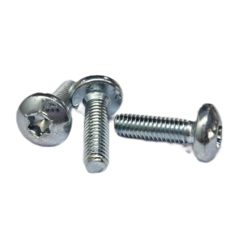
A screw-mounted PCB guide rail is mechanically fixed to the support structure using screws or threaded mounting points.
Compared with a pure snap-in design, screw fastening provides a more positive mechanical connection.
For example, guide rails may be mounted to horizontal rails or support plates using dedicated screws and threaded inserts. Commercial subrack systems commonly use support rails and horizontal rails as the mechanical interface for guide rails.
Advantages of Screw-Mounted Guide Rails
The main advantages include:
- Strong mechanical fixation
- Better resistance to movement
- Suitable for demanding applications
- More flexible positioning
- Easy to inspect mechanically
- Suitable for custom subrack structures
A screw-mounted guide rail can be particularly useful when the equipment may experience vibration, shock, transportation loads, or repeated PCB insertion and removal.
This is important in applications such as:
- Railway electronics
- Industrial automation
- Test and measurement equipment
- Power electronics
- Communication equipment
- Rugged embedded systems
Screw-Mounted Guide Rails for Replacement Projects
Screw-mounted guide rails can also be a practical choice for replacement and retrofit applications.
If the original guide rail is no longer available, a replacement guide rail can sometimes be attached to the existing horizontal rail or support plate using a compatible mounting configuration.
However, you should verify:
- Screw size
- Hole position
- Hole spacing
- Guide rail height
- PCB groove width
- PCB depth
- Mounting rail dimensions
A guide rail that looks similar may not be mechanically interchangeable.
3. Snap-In + Screw Fastening
Some guide rails provide both snap-in positioning and screw fastening.
This design combines the convenience of snap-in installation with the additional mechanical security of a screw.
The snap-in feature can position the guide rail during assembly, while the screw provides additional retention.
Why Use Combined Mounting?
This configuration can be useful when the equipment requires:
- Fast initial positioning
- Additional mechanical retention
- Better vibration resistance
- More secure long-term installation
- Flexible maintenance
It is particularly interesting for equipment where the guide rail must remain securely positioned under repeated mechanical loads.
Some commercial card guide systems explicitly provide versions for both snap-in and screw fastening.
Snap-In vs. Screw-Mounted Guide Rails
The following table provides a quick comparison.
| Feature | Snap-In | Screw-Mounted | Snap-In + Screw |
|---|---|---|---|
| Installation speed | Excellent | Moderate | Good |
| Tools required | Usually no | Yes | Usually yes |
| Mechanical retention | Good | Excellent | Excellent |
| Easy replacement | Excellent | Good | Good |
| Position adjustment | Good | Excellent | Excellent |
| Vibration resistance | Application dependent | High | Very high |
| Assembly cost | Low | Moderate | Moderate |
| High-volume production | Excellent | Good | Good |
| Rugged applications | Application dependent | Excellent | Excellent |
| Retrofit applications | Good | Excellent | Excellent |
The correct choice depends on the mechanical structure and operating environment rather than simply selecting the most secure mounting method.
How Does the PCB Guide Rail Mount to a 19-Inch Subrack?
A typical 19-inch subrack uses horizontal or support rails to create the mechanical mounting structure for the guide rails.
The general assembly relationship can be understood as:
19-Inch Subrack → Horizontal/Support Rail → PCB Guide Rail → PCB → Backplane
The guide rail establishes the position of the PCB relative to the backplane.
This means that guide rail mounting accuracy can directly affect connector alignment.
If the guide rail is installed at the wrong vertical position, the PCB may not enter the backplane connector correctly.
This can lead to:
- Difficult PCB insertion
- Excessive connector force
- PCB edge damage
- Connector misalignment
- Uneven mechanical loading
- Poor module positioning
For this reason, the guide rail should always be considered together with the subrack’s mechanical architecture.
PCB Guide Rail Mounting and IEC 60297
19-inch subrack systems are commonly designed around the mechanical architecture defined by the IEC 60297 series.
However, an important point for engineers is that IEC 60297 compatibility does not automatically mean that every PCB guide rail is interchangeable.
The 19-inch width is only one part of the mechanical system.
You still need to verify:
- Subrack height
- PCB height
- PCB depth
- PCB thickness
- Guide rail mounting position
- Guide rail lengthGroove width
- Horizontal rail configuration
- Backplane position
- Front panel position
Our previous guide on IEC 60297 and Eurocard compatibility explains why dimensional compatibility is particularly important when selecting replacement subrack components.
PCB Thickness: 1.6 mm vs. 2.0 mm
One of the most commonly overlooked parameters is PCB thickness.
Many Eurocard PCBs are approximately 1.6 mm thick, but some applications use thicker PCB assemblies.
For example:
1.6 mm PCB ≠ 2.0 mm PCB
The guide groove must provide the correct clearance for the PCB edge.
If the groove is too narrow, PCB insertion can become difficult.
If the groove is too wide, the PCB may move excessively inside the subrack.
Our PCB guide rail products are available for approximately 1.6–2.0 mm PCB thickness, depending on the model.
Therefore, when selecting a replacement guide rail, always measure the actual PCB thickness instead of assuming a standard dimension.
PCB Guide Rail Length
Guide rail length should match the PCB depth.
Common PCB depths in modular subrack systems include:
- 160 mm
- 220 mm
- 280 mm
- Custom lengths
For example, a 160 mm PCB normally requires a guide rail designed for approximately the same PCB depth.
A guide rail that is too short may not provide sufficient PCB support.
A guide rail that is too long may interfere with the backplane or other internal components.
The relationship between PCB depth and subrack frame depth should also be considered because the overall frame must accommodate the backplane, connectors, and rear wiring.
PCB Guide Rails for Railway and High-Vibration Applications
For railway and other high-vibration applications, guide rail selection becomes more important.
The guide rail must maintain PCB positioning while the equipment is exposed to vibration and shock.
In these applications, engineers should evaluate:
- Mounting strength
- Material
- Fire performance
- PCB retention
- Mechanical stability
- ESD/grounding requirements
- Compatibility with the subrack structure
For demanding environments, screw-mounted or combined mounting configurations may be preferable when the mechanical design requires additional retention.
For railway electronics, material and fire-performance requirements should also be evaluated according to the applicable equipment standard and project specification.
ESD and Grounding Options
PCB guide rails can also incorporate grounding or ESD-related features.
Some guide rail designs can accommodate an ESD clip, creating an electrical connection between the PCB edge area and the subrack structure.
This can be useful when the equipment requires controlled grounding or electrostatic discharge management.
The guide rail should therefore not be considered only as a mechanical component.
In some designs, it becomes part of the mechanical and electrical interface between the PCB and the subrack.
How to Choose the Right PCB Guide Rail Mounting Type
Before ordering a PCB guide rail, we recommend checking the following eight parameters.
1. PCB thickness
Confirm whether the PCB is 1.6 mm, 2.0 mm, or another thickness.
2. PCB depth
Typical options include 160 mm, 220 mm, and 280 mm, with custom lengths available.
3. Mounting method
Determine whether the original system uses:
- Snap-in
- Screw mounting
- Snap-in + screw
4. Mounting position
Measure the exact mounting position relative to the horizontal or support rail.
5. Guide groove width
Make sure the groove matches the actual PCB edge thickness.
6. Subrack height
Confirm whether the system is based on a 3U, 4U, 6U, or another configuration.
7. Operating environment
Consider whether the equipment is used in:
- Industrial control
- Telecom
- Railway
- Power systems
- Test equipment
- Data acquisition
- Rugged embedded systems
8. Replacement compatibility
If you are replacing an existing guide rail, compare the original component with the new one using actual dimensions rather than relying only on the product name.
Common PCB Guide Rail Mounting Problems
Problem 1: The guide rail does not fit the support rail
Possible cause: Different mounting geometry.
Solution: Check the mounting hole, snap-in feature, rail profile, and guide rail dimensions.
Problem 2: The PCB is difficult to insert
Possible causes:
- Incorrect groove width
- Incorrect guide rail position
- PCB thickness mismatch
- Backplane misalignment
Problem 3: The PCB moves too much
Possible causes:
- Groove is too wide
- Guide rail is not correctly secured
- Incorrect guide rail model
- Excessive mechanical tolerance
Problem 4: The PCB connector does not align with the backplane
Possible cause: Incorrect guide rail mounting height or horizontal position.
This is one of the most important reasons to check the entire mechanical stack-up before selecting a replacement guide rail.
Replacement PCB Guide Rails: What Should You Send to the Manufacturer?
If you cannot identify the original guide rail model, you do not necessarily need to provide the original part number.
A manufacturer can often evaluate the replacement based on:
- Original guide rail sample
- 2D drawing
- 3D CAD file
- PCB dimensions
- PCB thickness
- PCB depth
- Mounting hole dimensions
- Horizontal rail dimensions
- Photos of the existing assembly
At YiHui, PCB guide rails can be supplied as standard components or manufactured according to customer drawings, samples, and technical specifications.
This makes custom manufacturing particularly useful for obsolete equipment, retrofit projects, maintenance programs, and replacement parts.
Which PCB Guide Rail Mounting Type Is Best?
There is no single mounting method that is best for every 19-inch subrack.
Snap-in guide rails are ideal when fast, tool-free installation and easy replacement are priorities.
Screw-mounted guide rails are a better choice when stronger mechanical retention, flexible positioning, or demanding operating conditions are important.
Snap-in + screw fastening provides a combination of fast positioning and additional mechanical security.
The most important point is to select the guide rail based on the complete mechanical interface, not simply the fact that it is advertised as a “19-inch PCB guide rail.”
Before ordering, check the PCB thickness, PCB depth, groove width, mounting configuration, guide rail position, subrack height, and backplane alignment.
For replacement projects, providing a drawing, sample, or dimensional information can significantly reduce the risk of incompatibility.
Looking for the Right PCB Guide Rail?
YiHui supplies PCB guide rails for 19-inch subracks, Eurocard systems, and CompactPCI applications, with different lengths, groove widths, mounting configurations, materials, and optional coding/ESD features.
Standard and customized solutions are available for:
- 19-inch subracks
- Eurocard systems
- CompactPCI
- Industrial control
- Railway electronics
- Automated test systems
- Telecom equipment
- Replacement and retrofit projects
If you are replacing an existing PCB guide rail and are unsure which model you need, send us the original sample, drawing, or dimensions.
We can help identify a suitable replacement or develop a customized guide rail according to your mechanical requirements.
Contact YiHui for PCB Guide Rail Selection & Custom Manufacturing.