When working with 19-inch electronic equipment, you will often come across two terms: IEC 60297 and Eurocard.
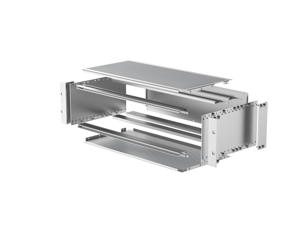
They are closely related, but they are not the same thing.
This distinction matters when you are designing a new subrack, replacing an old PCB guide rail, selecting a front panel, or trying to find a replacement for a discontinued component.
A component may look like a standard 19-inch part, but that does not necessarily mean it will fit your existing subrack.
So, what exactly is the relationship between IEC 60297 and Eurocard? And what should you check before ordering subrack components?
Let’s look at it from a practical engineering perspective.
What Does IEC 60297 Actually Define?
IEC 60297 is one of the key standards used for the mechanical construction of electronic equipment racks and subracks.
The familiar 19-inch rack is part of this standardized mechanical system. The nominal rack width is 482.6 mm.
But when engineers talk about IEC 60297 compatibility, they are not only talking about the 19-inch width.
The mechanical structure also involves dimensions and interfaces such as:
- Subrack width and height
- Front panel dimensions
- Mounting positions
- Card spacing
- PCB positioning
- Horizontal rails
- Guide rail locations
- Module installation
This standardization is one of the reasons why modular electronic equipment can be designed and maintained over many years.
For example, a telecom equipment manufacturer may design a system around a standardized subrack structure and later replace individual PCB assemblies without changing the entire enclosure.
That is one of the major advantages of a standardized mechanical platform.
So, Where Does Eurocard Come In?
Eurocard is best understood as a standardized PCB/module format used in modular electronic systems.
Instead of installing one large PCB inside an enclosure, a Eurocard-based system uses a number of individual circuit boards installed side by side.
A typical arrangement looks like this:
PCB → PCB guide rail → backplane → front panel → card extractor
The board slides along the guide rails and connects to the backplane at the rear of the subrack.
This modular approach is widely used in industrial electronics, telecom equipment, railway electronics, test systems, instrumentation, and other applications where individual boards may need to be replaced or upgraded.
You will commonly encounter 3U and 6U Eurocard configurations.
However, the PCB size is only one part of the equation.
The mechanical relationship between the PCB, guide rails, front panel, extractor, and backplane also needs to be correct
IEC 60297 and Eurocard Are Not the Same Standard
This is probably the most common point of confusion.
IEC 60297 is mainly concerned with the mechanical dimensions and structure of rack and subrack systems.
Eurocard refers to a standardized modular PCB format.
In a real product, they work together.
Think of it this way:
IEC 60297 provides the mechanical framework, while Eurocard provides a standardized way of arranging electronic modules within that framework.
This is why you may see products described as “19-inch IEC 60297 subrack,” “3U Eurocard subrack,” or similar terms.
The terminology can overlap, but the actual dimensions and interfaces still need to be checked.
Why “19-Inch Compatible” Is Not Enough
This is particularly important when buying replacement parts.
Suppose you have an existing 19-inch subrack and need a new PCB guide rail.
You find a product online described as:
“19-inch subrack PCB guide rail.”
It looks almost identical to the original part.
But after installation, the PCB does not line up correctly with the backplane.
Why?
Because the 19-inch dimension only tells you part of the story.
The guide rail may have a different:
- Mounting position
- PCB thickness
- Rail height
- Rail length
- Head shape
- Locking method
- Hole arrangement
Even a small difference can affect PCB alignment.
The same issue can occur with front panels, card extractors, horizontal rails, and other subrack accessories.
For replacement projects, dimensional compatibility is more important than the product name.
PCB Guide Rails: A Small Part With a Big Job
PCB guide rails are often overlooked during the initial design of a subrack.
In practice, they are critical.
The guide rail controls how the PCB enters the subrack and helps keep the board aligned with the backplane connector.
If the rail position is wrong, you may experience:
- Difficult PCB insertion
- Connector misalignment
- Excessive insertion force
- PCB edge damage
- Unstable board positioning
For this reason, when replacing a guide rail, don’t simply ask:
“Is this a 19-inch guide rail?”
Instead, check:
“Will this guide rail position my PCB at exactly the right height and depth for my existing backplane?”
That is the question that matters
3U and 6U Eurocard Systems
The two configurations you will encounter most often are 3U and 6U.
A 3U system is commonly used where a more compact modular architecture is required. A 6U system provides more vertical space and is often used for larger or more complex electronic assemblies.
The difference affects more than the PCB itself.
It also affects:
- Front panel height
- Guide rail arrangement
- Extractor dimensions
- Subrack structure
- Backplane configuration
- Available internal space
When ordering a replacement component, therefore, always specify whether you are working with a 3U or 6U system.
Front Panels Need to Match the PCB and Subrack
A front panel is not simply a piece of metal covering the front of the PCB.
It has several jobs.
It protects the electronics, provides a mounting interface, allows identification of the module, and can also contribute to the EMC performance of the enclosure.
For a Eurocard system, the panel needs to match the mechanical arrangement of the PCB and subrack.
Depending on the application, the panel may include:
- Card handles
- Extractor handles
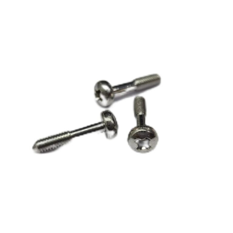
- Mounting screws
- Ventilation openings
- EMC grounding contacts
- Labels or identification areas
If you are replacing an original front panel, the mounting-hole location and panel dimensions should be checked carefully.
Card Extractors Make Maintenance Easier
If you have ever tried to remove a PCB from a densely populated backplane system, you will understand why card extractors are useful.
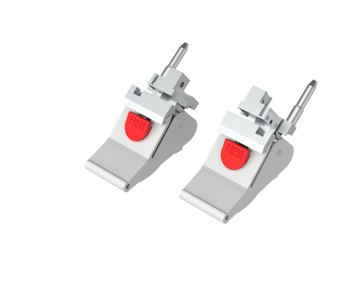
A card extractor provides mechanical leverage when inserting or removing a board.
This becomes particularly useful when the backplane connectors have relatively high mating forces.
Depending on the design, extractors can also help secure the PCB in its operating position.
For maintenance applications, a compatible extractor can make a noticeable difference to the service life of the PCB and connector.
This is one reason why many Eurocard systems use dedicated extractor handles rather than simply pulling the PCB by hand.
What About EMC Grounding?
Mechanical compatibility is only one part of subrack design.
For many electronic systems, EMC performance is equally important.
The front panel and subrack may need to maintain electrical continuity through components such as:
- EMC grounding clips
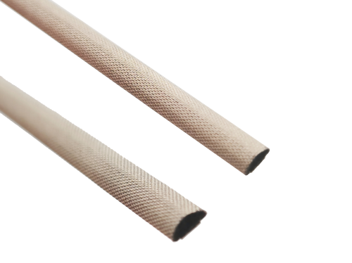
- Conductive fabric gaskets
- Metal mesh gaskets
- Grounding springs
- Conductive contact strips
These components help establish a conductive connection between the panel and the subrack frame.
The exact solution depends on the enclosure design, required shielding performance, materials, and environmental conditions.
For railway, telecom, industrial control, energy, and test equipment, EMC considerations should normally be addressed during the mechanical design stage rather than added at the end.
Can IEC 60297 Components Replace Schroff, Rittal or ELMA Parts?
This is a question we often see in the replacement-parts market.
The short answer is:
Sometimes, but don’t assume it from the brand or product description alone.
Different manufacturers may use similar 19-inch mechanical architectures, but individual components can still have different dimensions or mounting methods.
For example, a replacement PCB guide rail may look almost identical to an original component but use a different mounting hole arrangement.
The same applies to:
- Front panels
- Card extractors
- Guide rails
- Horizontal rails
- EMC grounding clips
- Mounting brackets
- Fasteners
If you are replacing a component from Schroff, Rittal, ELMA, or another manufacturer, the safest approach is to compare the actual dimensions and interface rather than relying only on the manufacturer’s name.
A drawing or sample is even better.
What Should You Check Before Ordering a Replacement?
If you are sourcing a replacement component for an existing subrack, we recommend checking these items first.
1. Subrack size
Is it:
- 19-inch
- 3U
- 6U
- Another configuration?
2. PCB dimensions
Check:
- PCB height
- PCB width
- PCB thickness
- PCB depth
3. Mounting dimensions
Look at:
- Hole spacing
- Hole diameter
- Mounting position
- Rail position
4. Interface dimensions
For components such as guide rails and extractors, check how they interact with the PCB and backplane.
5. Material
Depending on the application, the component may be made from:
- Aluminum
- Steel
- Stainless steel
- Engineering plastic
- Die-cast zinc
6. Environmental requirements
For demanding applications, you may also need to consider:
- Vibration
- Shock
- Temperature
- Fire performance
- EMC requirements
- Corrosion resistance
A replacement part that fits mechanically may still not be suitable for the operating environment.
IEC 60297 vs. IEC 61587
These two standards are sometimes mentioned together because they address different aspects of electronic equipment structures.
In simple terms:
IEC 60297 is mainly about mechanical dimensions and interfaces.
IEC 61587 addresses environmental and mechanical performance of electronic equipment structures.
So when developing a subrack for a demanding application, there are really two separate questions:
Will everything fit?
and
Will the structure survive the required operating environment?
For applications such as railway electronics, industrial control, energy systems, and transportation equipment, both questions can be important.
Where Are Eurocard Subracks Used?
The Eurocard/subrack concept continues to be useful in applications where modularity and maintainability matter.
Typical applications include:
Railway Electronics
Railway signaling, communication, control, and onboard electronic systems often require rugged modular construction.
Telecom
Telecommunication equipment can use modular PCBs to simplify system configuration and maintenance.
Industrial Automation
Control systems can be divided into individual modules, making troubleshooting and replacement easier.
Automated Test Equipment
ATE systems often use modular architectures because different testing functions may require different electronic boards.
Power and Energy Systems
Protection, monitoring, control, and automation equipment can benefit from standardized mechanical platforms.
A Practical Way to Think About Compatibility
When evaluating a Eurocard component, don’t start with the product name.
Start with the interface.
Ask:
Where does the PCB sit?
How is the PCB guided?
Where does the backplane connector sit?
How is the front panel mounted?
How is the PCB extracted?
How is EMC grounding achieved?
Once these interfaces are understood, it becomes much easier to determine whether a component is genuinely compatible.
This approach is particularly useful when sourcing replacement parts for older equipment where the original component is no longer available.
IEC 60297 and Eurocard have played an important role in creating modular and maintainable electronic equipment.
But “19-inch” or “Eurocard compatible” should never be treated as a complete compatibility specification.
The actual dimensions of the PCB, guide rail, front panel, extractor, backplane, and mounting structure all need to work together.
For new subrack designs, checking these interfaces at the beginning can prevent expensive redesign work later.
For replacement projects, comparing the original component drawing, dimensions, or physical sample is usually the fastest way to find a suitable alternative.
At SubrackParts, we focus specifically on components for 19-inch subrack systems, including PCB guide rails, PCB extractors, front panels, EMC/EMI grounding components, mounting hardware, and custom subrack parts.
If you have an existing component that needs to be replaced, send us the part number, drawing, dimensions, or photos. We can help evaluate the mechanical requirements and develop a compatible replacement where needed.