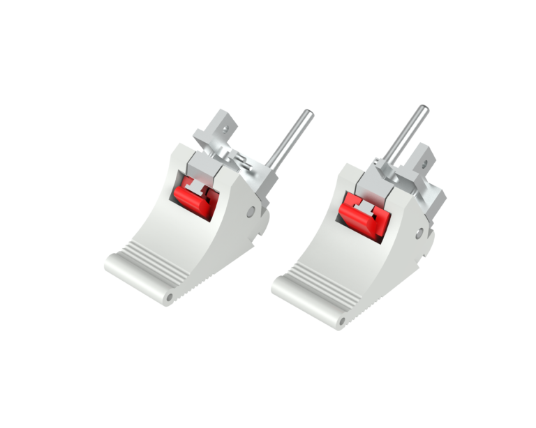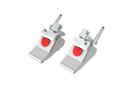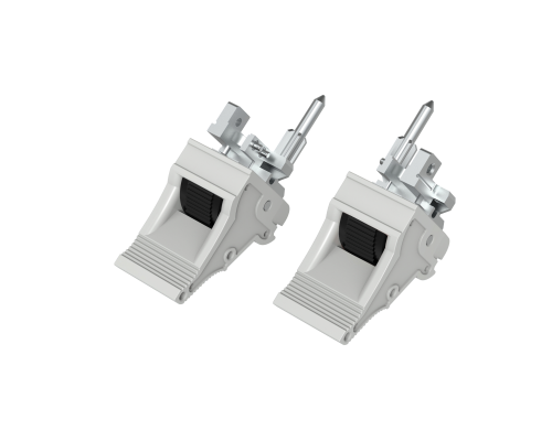
A PCB extractor is a small but important mechanical component in Eurocard and 19-inch subrack systems. It allows operators to insert and remove plug-in PCBs more easily while helping protect the PCB, backplane connector, and front-panel assembly.
For engineers working with 3U and 6U Eurocard systems, VME, CompactPCI, industrial control equipment, telecom systems, railway electronics, and automated test equipment, choosing the correct PCB extractor is more than simply finding a handle that looks similar.
The extractor must match the PCB thickness, mounting position, front-panel design, connector requirements, available operating space, and overall subrack architecture.
For replacement projects, the challenge is even greater. An extractor that appears identical may have a different mounting hole position, lever geometry, or operating angle and therefore may not work correctly with the existing PCB assembly.
This guide explains how to select a PCB extractor for a new Eurocard design—and, more importantly, how to choose a replacement PCB extractor for an existing system.
What Is a PCB Extractor?
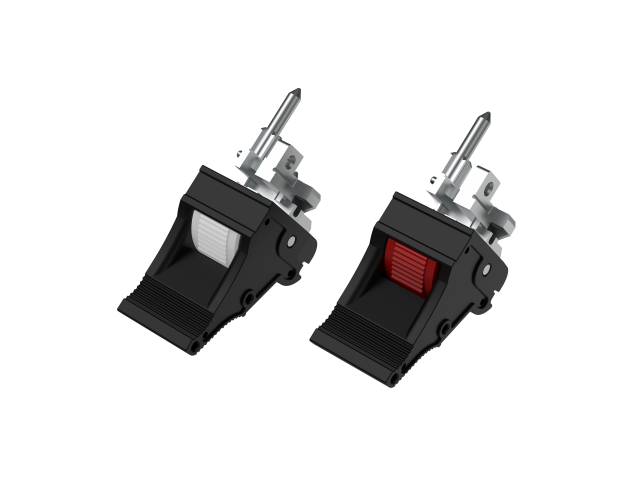
A PCB extractor, also called a PCB ejector, PCB extractor handle, or card ejector, is a mechanical device attached to a plug-in printed circuit board or its front-panel assembly.
Its primary function is to provide mechanical leverage during board insertion and removal.
Instead of pulling directly on the PCB or connector, the operator uses the extractor lever to generate controlled mechanical force.
A typical extractor can help with:
- PCB insertion
- PCB extraction
- Connector engagement and disengagement
- Module retention
- Operator handling
- Board identification
- Maintenance and replacement
In systems with high-density backplane connectors, this mechanical assistance can be particularly important because connector insertion and extraction forces can be relatively high.
Why Is PCB Extractor Selection Important?
A PCB extractor may represent only a small percentage of the total cost of a subrack assembly, but an incorrectly selected extractor can create significant mechanical problems.
For example, an incompatible extractor may cause:
- Insufficient extraction force
- Difficulty removing the PCB
- Interference with adjacent modules
- Misalignment with the front panel
- Excessive stress on the PCB
- Damage to the backplane connector
- Poor board retention
- Reduced maintenance efficiency
This is why the extractor should be treated as part of the complete mechanical interface rather than as an independent accessory.
The basic relationship is:
PCB + Extractor + Guide Rail + Front Panel + Connector + Subrack
All of these components should work together.
1. Start With the Eurocard Format
The first step is to identify the PCB format.
Eurocard-based systems commonly use 3U and 6U board formats within 19-inch subrack architectures.
Typical Eurocard dimensions include:
| Parameter | Typical 3U Eurocard | Typical 6U Eurocard |
|---|---|---|
| Board height | 100 mm | 233.35 mm |
| Common depth | 160 mm | 160 mm |
| Typical PCB thickness | 1.6 mm | 1.6 mm |
| Typical application | Compact modules | Larger plug-in modules |
Actual dimensions may vary depending on the system architecture and application.
Before selecting an extractor, confirm:
- PCB height
- PCB depth
- PCB thickness
- Front-panel height
- Front-panel thickness
- Mounting-hole position
- Connector position
Do not select an extractor based only on the terms “3U” or “6U.”
The overall board format is only the starting point.
2. Check the PCB Thickness
PCB thickness is one of the most important dimensions when selecting an extractor.
A large number of Eurocard PCBs use approximately 1.6 mm thickness, but thicker boards and reinforced PCB assemblies are also possible.
The extractor, guide rail, and PCB mounting arrangement must accommodate the actual board thickness.
For example:
1.6 mm PCB ≠ 2.0 mm PCB ≠ 2.4 mm PCB
Even a relatively small dimensional difference can affect the fit between the PCB and the guide rail or extractor assembly.
When purchasing replacement parts, measure the original PCB rather than assuming that it uses a standard thickness.
3. Understand the Extractor Mechanism
Different PCB extractors use different lever and pivot mechanisms.
A good extractor should provide sufficient mechanical advantage to disengage the PCB connector without requiring excessive manual force.
When comparing extractor designs, consider:
Lever ratio
A longer or better-positioned lever can provide greater mechanical advantage.
Pivot location
The pivot geometry affects both extraction force and operating movement.
Operating angle
The extractor should have enough clearance to operate without hitting adjacent components.
Locking mechanism
A locking feature can help prevent accidental movement or board disengagement.
Return mechanism
Some designs incorporate spring or positioning features to maintain the extractor in a defined position.
For high-density modular equipment, the mechanism should be evaluated together with the connector and front-panel structure.
4. Check the Front Panel Compatibility
The PCB extractor is often mechanically connected to or positioned alongside the front panel.
This means the extractor cannot be selected independently from the front-panel design.
Check the following:
- Mounting-hole spacing
- Hole diameter
- Panel thickness
- Extractor height
- Lever position
- Operating clearance
- Adjacent component clearance
- Front-panel handle position
A technically correct PCB extractor may still be unsuitable if its lever interferes with the front panel or neighboring modules.
5. Consider Connector Extraction Force
The backplane connector is one of the main reasons PCB extractors are used.
A plug-in board with a high-density connector can require significant force to disengage.
Without an extractor, technicians may attempt to pull the board directly, potentially applying uneven force.
A suitable extractor transfers the operator’s force through the mechanical lever system.
This can provide:
- Easier board removal
- More controlled extraction
- Reduced connector stress
- Reduced PCB stress
- Better maintenance ergonomics
For systems designed for frequent servicing, the extractor mechanism should therefore be selected according to the connector and expected insertion/extraction frequency.
6. Consider Locking and Keying
For systems containing multiple plug-in modules, locking and keying can be important.
Locking
A locking mechanism can help keep the PCB securely positioned during operation and transportation.
This is particularly useful for equipment exposed to:
- Vibration
- Shock
- Transportation
- Frequent handling
Keying
Keying or coding can help prevent a module from being inserted into the wrong slot.
This can be useful in:
- Industrial control
- Telecom equipment
- Railway electronics
- Automated test systems
- Power electronics
- Modular instrumentation
For mission-critical equipment, mechanical keying can provide an additional layer of protection against incorrect module installation.
7. Consider the Operating Environment
The correct extractor for a laboratory instrument may not be the best choice for railway or industrial equipment.
Consider the operating environment:
| Application | Important Considerations |
|---|---|
| Laboratory equipment | Ergonomics, cost, appearance |
| Industrial control | Strength, reliability, serviceability |
| Telecom | Frequent maintenance, retention |
| Railway electronics | Vibration, shock, retention |
| Automated test equipment | Frequent insertion/removal |
| Power electronics | Thermal and mechanical reliability |
| Rugged electronics | Strength, locking, environmental resistance |
For demanding applications, extractor selection should be evaluated together with the applicable system-level mechanical requirements.
8. Select the Right Material
Material selection affects mechanical strength, weight, durability, and cost.
Common materials include:
Engineering plastics
Plastic extractors are lightweight and electrically insulating. They can be suitable for many standard modular electronic systems.
Aluminum
Aluminum provides a combination of low weight and good mechanical strength. Surface treatments such as anodizing can improve corrosion resistance and appearance.
Zinc alloy
Die-cast zinc can provide a rigid and durable mechanical structure and is useful where a robust lever mechanism is required.
The best material depends on:
- Extraction force
- Operating temperature
- Vibration
- Expected service life
- Weight requirements
- Cost target
- Surface-finish requirements
How to Choose a Replacement PCB Extractor?
This is one of the most important considerations when maintaining an existing Eurocard or 19-inch subrack system.
A replacement PCB extractor should not be selected based only on appearance.
Two extractors can look almost identical but have different mechanical dimensions.
For replacement applications, the objective is to find a component that matches the mechanical interface and operating function of the original part.
Step 1: Identify the Original Extractor
First, collect as much information as possible about the existing extractor.
Look for:
- Manufacturer
- Part number
- Product series
- Material
- Dimensions
- Markings
- Mounting method
If the original extractor is no longer available, photographs and measurements can help identify a suitable replacement.
Step 2: Measure the Mounting Dimensions
This is usually the most important step.
Measure:
- Overall extractor length
- Overall extractor height
- Width
- Mounting-hole diameter
- Hole-to-hole distance
- Pivot-hole position
- Mounting screw size
- Distance from PCB edge
- Distance from front-panel edge
A replacement extractor with the wrong mounting-hole position may not be mechanically interchangeable even if it has the same general appearance.
Step 3: Measure the PCB Thickness
Measure the actual PCB thickness using a caliper.
Do not rely only on the original equipment documentation.
For example, if the existing board is approximately 1.6 mm thick, confirm that the replacement extractor and guide rail combination is designed for this configuration.
If the board is thicker or thinner, a different extractor configuration may be required.
Step 4: Check the Front-Panel Geometry
The front panel can determine whether the replacement extractor will operate correctly.
Check:
- Panel thickness
- Panel height
- Extractor mounting position
- Lever clearance
- Screw position
- Distance to adjacent panels
- Available operating space
This is particularly important when replacing extractors in densely populated subracks.
Step 5: Compare the Lever Movement
Do not only compare static dimensions.
Compare how the original extractor actually operates.
Ask:
Does the lever rotate, pivot, or slide?
What is the operating angle?
Where is the pivot point?
How far does the extractor move
Does the mechanism push or pull the PCB?
The replacement must generate the correct mechanical movement.
Step 6: Check Connector Requirements
A replacement extractor must provide enough mechanical leverage for the connector being used.
If the original extractor was designed for a high-force connector, replacing it with a lightweight or low-leverage design may make board removal difficult.
Therefore, identify the backplane connector whenever possible.
Useful information includes:
- Connector manufacturer
- Connector series
- Number of contacts
- Insertion/extraction force
- Connector position
Step 7: Check Adjacent Components
In a densely populated subrack, even a few millimeters can make a difference.
Check whether the replacement extractor interferes with:
- Adjacent PCBs
- Front panels
- LEDs
- Switches
- Handles
- EMC gaskets
- Guide rails
- Mounting screws
This is especially important when replacing parts in older systems where documentation may no longer be available.
Standard Replacement or Custom Replacement?
Not every replacement application requires a completely new design.
There are generally three approaches.
1. Direct replacement
The new extractor matches the original dimensions and mechanism.
This is the simplest solution.
2. Compatible replacement
The new extractor may have a different appearance but uses the same critical mounting and operating dimensions.
This can be useful when the original manufacturer has discontinued the product.
3. Custom replacement
A new extractor is designed according to the customer’s PCB and front-panel dimensions.
Custom replacement can be particularly useful when:
- Original parts are obsolete
- The original supplier no longer supports the product
- Minimum order quantities are too high
- Replacement parts are difficult to source
- The customer needs a modified material
- A different color or surface treatment is required
- Existing equipment needs to be upgraded
PCB Extractor Replacement: What Information Should You Send a Supplier?
If you are looking for a replacement PCB extractor, providing the supplier with complete information can significantly reduce communication time.
Ideally, provide:
1. Original extractor photos
Take photos from the front, side, and rear.
2. PCB thickness
For example:
PCB thickness: 1.6 mm
3. Mounting dimensions
Provide hole diameter and hole-to-hole distance.
4. Front-panel drawing
A simple 2D drawing is sufficient if a formal CAD file is unavailable.
5. Overall dimensions
Length × width × height.
6. Existing application
For example:
6U Eurocard / VME / CompactPCI / industrial control
7. Quantity
Replacement projects and OEM production may require different sourcing solutions.
With these details, a manufacturer can usually determine whether a standard extractor is suitable or whether a custom replacement is required.
IEC 60297 Compatibility: What Does It Really Mean?
IEC 60297 provides dimensional specifications for mechanical structures used in 19-inch electronic equipment.
It is highly relevant to Eurocard-based subrack systems.
However, an extractor should not be considered interchangeable simply because both products are described as IEC 60297 compatible.
IEC 60297 defines the overall mechanical architecture, while the actual extractor interface can depend on the specific PCB, front panel, guide rail, connector, and manufacturer design.
Therefore:
IEC 60297 compatibility is a starting point—not a guarantee of direct replacement.
For replacement applications, always compare the actual mechanical dimensions.
PCB Extractor Selection Checklist
Before purchasing a PCB extractor, check the following:
- 3U, 6U, or other PCB format
- PCB depth
- PCB thickness
- Front-panel dimensions
- Mounting-hole spacing
- Mounting-hole diameter
- Extractor overall dimensions
- Pivot position
- Lever operating angle
- Required extraction force
- Locking requirements
- Keying requirements
- Material
- Surface finish
- Operating temperature
- Vibration and shock requirements
- IEC 60297-based mechanical architecture
- OEM or replacement requirement
When Should You Choose a Custom PCB Extractor?
A custom extractor may be the better solution when a standard product cannot satisfy the mechanical interface.
Typical situations include:
Obsolete equipment
The original extractor has been discontinued.
Legacy systems
The original manufacturer no longer provides spare parts.
Special PCB thickness
The PCB does not match common thickness specifications.
Special front-panel design
The available space does not accommodate standard extractors.
High-force connectors
The application requires a stronger or different lever mechanism.
OEM production
The customer needs a dedicated extractor for a new equipment platform.
Brand or appearance requirements
The customer requires a specific logo, color, surface treatment, or packaging.
A custom PCB extractor can often be developed from an existing standard mechanism with modifications to the mounting geometry.
Final Thoughts
Choosing the right PCB extractor for a Eurocard system requires more than matching the board height or finding a visually similar handle.
For a new design, evaluate the complete mechanical interface:
PCB → Extractor → Guide Rail → Front Panel → Connector → Subrack
For replacement applications, focus even more closely on the original component’s:
dimensions + mounting holes + pivot position + lever movement + PCB thickness + connector requirements.
If you are replacing an obsolete PCB extractor, you do not necessarily need to replace the entire subrack or PCB assembly.
A compatible replacement extractor can often extend the service life of existing equipment while reducing maintenance cost and downtime.
For 3U/6U Eurocard, VME, CompactPCI, industrial control, telecom, railway, and automated test equipment, a specialized subrack accessory supplier can evaluate the original component and provide either a compatible standard replacement or a customized solution.
Need a Replacement PCB Extractor?
If you cannot identify the original PCB extractor, send the following information to the supplier:
① Photos of the original extractor
② PCB thickness
③ Extractor dimensions
④ Mounting-hole spacing
⑤ Front-panel dimensions
⑥ Application and subrack format
⑦ Required quantity
With these details, the supplier can check compatibility and recommend a suitable replacement.
Looking for a replacement PCB extractor for your Eurocard system? Contact YiHui with your existing part dimensions or photos for a compatibility check.