A Eurocard backplane is the board or assembly installed at the rear of a modular electronic system to connect Eurocard PCBs.
You will usually find one inside a 19-inch subrack, Eurocard chassis, VME system, or other modular equipment. The plug-in boards slide into the chassis from the front, and their rear connectors mate with connectors mounted on the backplane.
The idea is straightforward: instead of wiring each board individually, the backplane provides a fixed interface for several boards.
For equipment that needs to be repaired, upgraded, or expanded over many years, this modular approach can be very practical.
How Does a Eurocard Backplane Work?
Think of a typical Eurocard system from front to back.
A PCB is inserted from the front of the subrack and guided into position by PCB guide rails. As the board reaches the rear, its connector mates with a connector on the backplane.
The basic arrangement is:
Eurocard PCB → Backplane Connector → Backplane
The backplane may then connect the board to other boards, power, I/O connections, or the rest of the system.
The actual circuit design depends on the application. Some backplanes are relatively simple passive boards. Others are designed for specific bus architectures and can have a much more complicated electrical layout.
From a mechanical point of view, however, the same issue remains: the PCB and backplane connectors have to line up accurately.
That is why the backplane cannot be considered separately from the guide rails, PCB dimensions, connector position, and card pitch.
Why Is It Called a Eurocard Backplane?
The term “Eurocard” refers to a modular PCB format that became widely used in European electronic equipment and later became common internationally.
Eurocard systems are closely associated with standardized board dimensions and modular subrack construction.
A Eurocard PCB is normally installed vertically in a card cage or subrack, with several boards positioned side by side.
The backplane provides the common connection interface at the rear.
This gives equipment designers a convenient way to build a system from individual plug-in boards rather than putting all the electronics onto one large PCB.
Eurocard Backplane and 19-Inch Subrack
A Eurocard backplane is often used together with a 19-inch subrack.
But the terms describe different things.
The 19-inch subrack is the mechanical enclosure or framework.
The Eurocard is the plug-in PCB format.
The backplane is the rear interface that connects the boards.
Other parts complete the system, including:
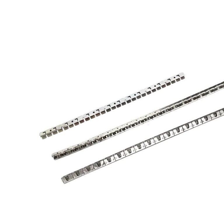
- PCB guide rails
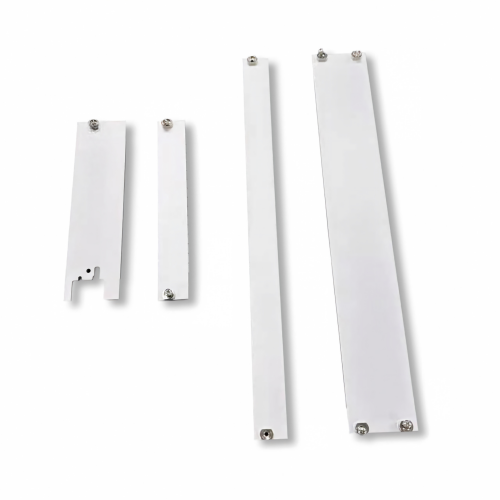
- Front panels
- PCB handles
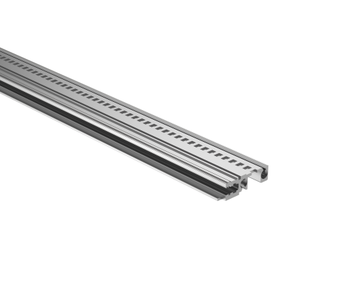
- Horizontal rails
- Mounting hardware
- Backplane connectors
This distinction is useful when sourcing replacement parts.
For example, someone may say:
“We need a replacement Eurocard backplane.”
But to manufacture or replace it, the supplier may also need information about the subrack, PCB dimensions, connector arrangement, and mounting pattern.
3U and 6U Eurocard Backplanes
One of the first specifications you will encounter is the board height.
3U and 6U are common formats in modular electronic systems.
A 3U Eurocard system is relatively compact and is commonly used where board height and available PCB area are limited.
6U systems provide more board height and are often used in larger systems such as VME-based equipment, industrial computers, test systems, and other modular electronics.
However, knowing that a backplane is “3U” or “6U” does not identify the backplane completely.
Two 3U backplanes can have completely different connector layouts.
For a replacement, you may also need to check:
- Number of slots
- Board pitch
- Connector type
- Connector position
- Mounting holes
- PCB dimensions
- Rear I/O arrangement
So 3U / 6U is a mechanical starting point, not a complete backplane specification.
What Connectors Are Used on a Eurocard Backplane?
DIN 41612 connectors are commonly associated with Eurocard and backplane applications. The IEC 60603-2 family covers a range of connectors used in electronic equipment, including configurations commonly found in Eurocard systems.
There are different connector configurations, so “DIN 41612 connector” by itself is still too general when selecting a replacement.
You may need to identify:
- Connector type
- Number of contacts
- Number of rows
- Plug or receptacle
- Contact arrangement
- Mounting style
- Termination method
- Mating connector
For example, a 96-position connector is not necessarily interchangeable with every other 96-position Eurocard connector.
The connector has to match both the electrical design and the mechanical layout.
Eurocard Backplane vs. Standard PCB
A Eurocard backplane is not simply a larger PCB.
Its design is driven by the relationship between several boards and the mechanical structure of the subrack.
A normal PCB may be designed primarily around its own components and electrical functions.
A backplane has additional constraints.
The connector positions must correspond to the positions of the plug-in boards. The mounting holes must line up with the subrack. The board pitch needs to match the guide rails. The rear side may also need to accommodate I/O connectors or cables.
This is why a backplane replacement project often requires both electrical information and mechanical information.
Why Board Pitch Matters
Board pitch is the distance between adjacent card positions.
It affects how many boards can fit into the subrack and where the connectors need to be located on the backplane.
For example, if the original system has a specific card pitch and the replacement backplane uses a different spacing, the PCB guide rails and connectors will no longer line up correctly.
This is an easy detail to overlook when ordering a replacement.
When measuring an existing system, it is useful to record the distance between adjacent PCB positions rather than relying only on the overall backplane width.
What Is the Difference Between a Eurocard Backplane and a VME Backplane?
These terms are related, but they are not necessarily interchangeable.
Eurocard primarily describes the mechanical and board format.
VME refers to a particular computer bus architecture that uses Eurocard-style boards and associated connector arrangements.
A VME backplane therefore has electrical and connector requirements associated with the VME architecture.
This distinction matters when sourcing replacement parts.
If a customer says they need a “Eurocard backplane,” there may not be enough information to identify the exact electrical configuration.
If they say it is a VME backplane, that provides additional information about the system architecture, but the specific connector arrangement and board layout still need to be checked.
Passive vs. Active Eurocard Backplanes
Not every Eurocard backplane has the same electrical complexity.
Passive Backplane
A passive backplane mainly provides electrical connections between the plug-in boards and does not normally contain significant active processing circuitry.
This type of design is useful in modular systems where the processing and control functions are located on the individual boards.
Active Backplane
An active backplane can contain additional electronic components or circuitry.
Depending on the application, it may perform functions related to switching, signal distribution, management, or other system functions.
For a replacement project, knowing whether the original backplane is passive or active is important before assuming that a mechanically similar board will work.
When Would You Replace a Eurocard Backplane?
There are several situations where replacement makes sense.
The Original Backplane Is Damaged
A damaged PCB, connector, or mounting area can make an otherwise usable subrack difficult to operate.
The Original Part Is Obsolete
This is common with older industrial and test equipment.
The equipment may still be in service even though the original backplane is no longer available.
The System Is Being Upgraded
Sometimes the chassis and mechanical structure are still suitable, but the electronics need to be changed.
A new backplane can provide a way to accommodate a different board arrangement or connector configuration.
A Custom Backplane Is Required
Some systems were never based on a standard backplane.
The manufacturer may have used a custom PCB size, connector arrangement, mounting pattern, or I/O configuration.
In these cases, a replacement may need to be developed from an existing sample or drawing.
What Information Is Needed for a Replacement?
If you are trying to replace an existing Eurocard backplane, start with the information that is available.
The following can be particularly helpful:
Backplane dimensions
3U or 6U height
Number of card positions
Board pitch
Connector type
Connector positions
Mounting-hole locations
PCB thickness
Existing part number
Photos of the original backplane
PCB or backplane drawing
You do not necessarily need to have every measurement before contacting a supplier.
A clear photograph of the complete backplane and several close-ups can be enough to start identifying the design.
If you have an original sample, that is even better.
Designing a Custom Eurocard Backplane
A custom backplane is usually designed around the actual requirements of the equipment.
The process may start with the PCB dimensions and card positions, followed by the connector arrangement and mounting requirements.
The supplier may also need information about:
- Number of slots
- Connector types
- Pin assignments
- Power requirements
- Signal requirements
- Rear I/O
- Mounting method
- PCB thickness
- Required materials and finish
For an existing system, the original backplane is often the most useful reference.
Instead of redesigning everything from scratch, the new part can be developed around the existing mechanical interfaces where appropriate.
Eurocard Backplanes and Long-Term Maintenance
One reason modular subrack systems remain useful is that individual boards and mechanical components can be replaced without rebuilding the entire equipment.
This is particularly valuable for industrial equipment, railway electronics, telecom systems, measurement equipment, and test systems that may remain in operation for many years.
The challenge comes when one small component becomes obsolete.
A replacement backplane, connector, guide rail, or front panel can sometimes be enough to keep an older system maintainable.
For this reason, replacement parts should be considered not only during the original design stage but also as part of the equipment’s long-term maintenance strategy.
Final Thoughts
A Eurocard backplane is the connection point between the plug-in boards and the rest of a modular electronic system.
It works together with the Eurocard PCB, backplane connector, PCB guide rail, card pitch, and subrack structure. A problem with any one of these interfaces can affect the whole assembly.
If you are specifying a new backplane, the electrical architecture and mechanical design need to be considered together.
If you are replacing an existing one, start with the original part. The part number, connector details, dimensions, drawing, or photographs can provide enough information to determine what needs to be reproduced or modified.
Need a Replacement Eurocard Backplane or Connector?
If the original part is obsolete or difficult to identify, send us the part number, drawing, dimensions, PCB layout, or photos.
We can help check the requirements for Eurocard backplanes, DIN 41612 connectors, PCB guide rails, horizontal rails, front panels, and other 19-inch subrack components.
Tell us what you have, and we can start from the existing part.