When engineers look for a replacement part for a VME, CompactPCI, or PXI chassis, one question often comes up:
Are these chassis compatible with IEC 60297?
The short answer is: they are closely related to the IEC 60297 and Eurocard mechanical architecture, but VME, CompactPCI, and PXI should not be treated as electrically interchangeable systems.
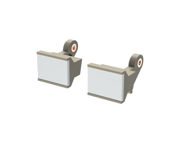
For mechanical components such as front panels, card guides, guide rails, handles, mounting hardware, and EMC grounding parts, understanding the relationship between these standards is important when selecting replacement or custom subrack components.
What Is IEC 60297?
IEC 60297 is a series of standards covering the mechanical structure of 482.6 mm (19-inch) equipment systems.
The standard family defines important mechanical dimensions used in electronic equipment racks, subracks, chassis, plug-in units, and related components.
A typical 19-inch subrack may include:
- Front panels
- Horizontal rails
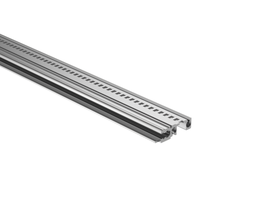
- PCB guide rails
- Card guides
- Backplanes
- Plug-in units
- Handles and extractors
- Mounting hardware
- EMC grounding components
IEC 60297 is primarily a mechanical standard. It should therefore not be confused with a bus or communication standard.
This distinction is important when comparing VME, CompactPCI, and PXI.
Are VME Chassis Compatible with IEC 60297?
Generally, VME systems use the Eurocard-based mechanical architecture associated with the 19-inch subrack system.
VMEbus was developed around Eurocard-style boards and rack-mounted systems. VME boards are commonly used in 3U and 6U formats, making them closely related to the mechanical dimensions used in 19-inch subracks.
However, VME is not simply another name for IEC 60297.
VME primarily defines the computer bus and electrical architecture, while IEC 60297 addresses mechanical dimensions.
Therefore:
VME = electrical/bus architecture + Eurocard-based mechanical implementation
IEC 60297 = mechanical framework for 19-inch equipment systems
This distinction becomes particularly important when replacing individual mechanical components.
For example, a VME chassis may use guide rails and front panels that follow the relevant Eurocard mechanical dimensions, but the exact component dimensions, mounting method, PCB thickness, and connector position still need to be checked before selecting a replacement.
Are CompactPCI Chassis Compatible with IEC 60297?
CompactPCI systems are also based on the Eurocard form factor.
CompactPCI uses 3U and 6U boards and is designed for rack-mounted embedded computing and industrial applications.
Its mechanical architecture is closely associated with the IEEE 1101 family of standards and the 19-inch Eurocard system.
This means that CompactPCI chassis can be considered part of the broader Eurocard/19-inch mechanical ecosystem.
However, CompactPCI adds its own electrical and backplane requirements.
For example, a CompactPCI system may have:
- 3U or 6U boards
- CompactPCI backplanes
- PCI-based architecture
- Specific connector arrangements
- Defined board insertion and extraction mechanisms
Therefore, the fact that a chassis is mechanically based on the Eurocard format does not mean that every VME or PXI backplane can be used in the same chassis.
Are PXI Chassis Compatible with IEC 60297?
PXI is particularly interesting because it was developed using the CompactPCI mechanical architecture.
PXI systems use the Eurocard form factor and are commonly available in 3U and 6U configurations.
PXI adds instrumentation-specific features such as:
- Triggering
- Timing
- Synchronization
- Reference clocks
- High-speed measurement infrastructure
From a mechanical perspective, PXI therefore has a strong relationship with the CompactPCI and Eurocard ecosystem.
However, PXI should not be treated as simply another name for CompactPCI.
A PXI chassis can have a mechanical architecture compatible with the Eurocard/subrack family while still requiring a specific PXI backplane and electrical infrastructure.
VME vs. CompactPCI vs. PXI
The easiest way to understand the relationship is to separate mechanical compatibility from electrical compatibility.
| System | Eurocard-based | 3U/6U | 19-inch applications | IEC 60297 relationship |
|---|---|---|---|---|
| VME | Yes | Yes | Yes | Closely related mechanical architecture |
| CompactPCI | Yes | Yes | Yes | Closely related mechanical architecture |
| PXI | Yes | Yes | Yes | Based on CompactPCI mechanical architecture |
The important point is that mechanical compatibility does not automatically mean electrical or functional compatibility.
Two systems may use the same basic 3U or 6U Eurocard dimensions while having completely different backplanes, connectors, signal assignments, and bus architectures.
Can the Same PCB Guide Rail Be Used for VME, CompactPCI and PXI?
Sometimes, but not automatically.
A PCB guide rail is a mechanical component. Its compatibility depends on several dimensions and mounting conditions.
Before replacing a guide rail, check:
1. PCB thickness
Common PCB thicknesses may include 1.6 mm and 2.0 mm, but the actual board thickness should always be confirmed.
2. PCB height
A 3U and 6U board require different guide rail arrangements.
3. Guide rail length
The guide rail must match the chassis depth and PCB insertion path.
4. Mounting method
Common mounting methods include:
- Snap-in
- Screw-mounted
- Clip-mounted
- Custom mounting
5. Hole spacing
The mounting-hole pattern must match the subrack rail or chassis structure.
6. Backplane position
The guide rail must position the PCB correctly so that the board connector aligns with the backplane connector.
This is especially important in systems where connector alignment tolerances are tight.
Can VME, CompactPCI and PXI Front Panels Be Interchanged?
Not necessarily.
Although these systems may use similar Eurocard dimensions, the front panel design can vary according to:
- Board height
- Board width
- Handle position
- Extractor design
- Screw location
- EMC requirements
- Connector openings
- Ejector/injector mechanism
For replacement work, the safest approach is to compare the original part with the replacement using a drawing, dimensions, or physical sample.
A replacement front panel that has the correct nominal height but incorrect hole positions may still be unusable.
What About PCB Extractor and Injector Handles?
VME, CompactPCI, and PXI systems can all use mechanical handles or extractors to assist with board insertion and removal.
However, the handle design depends on the board and chassis configuration.
Important parameters include:
- Handle height
- Mounting hole position
- Screw size
- Rotation angle
- Board thickness
- Connector insertion force
- Available front-panel space
Therefore, a handle should be selected according to the actual board and chassis rather than only by the system name.
What About EMC Grounding?
EMC is another area where mechanical compatibility and electrical performance overlap.
A front panel may need to establish electrical continuity with the chassis through:
- Conductive gaskets
- EMC fingers
- Grounding clips
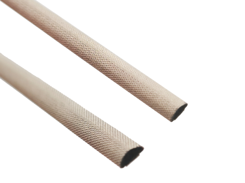
- Conductive fabric
- Metal contact surfaces
The mechanical dimensions determine whether a component fits, while the material and contact design affect the electrical connection.
For this reason, replacing an EMC component requires more than checking its length and width.
The contact area, compression, material, surface treatment, and grounding path may also need to be considered.
Does IEC 60297 Mean That All 19-Inch Subrack Parts Are Interchangeable?
No.
This is one of the most important points to remember.
IEC 60297 provides a mechanical framework, but manufacturers and system designers can use different:
- Chassis depths
- Rail designs
- Mounting systems
- Guide rail profiles
- Front panel configurations
- Backplane positions
- Handles
- EMC solutions
A component may therefore be designed for a 19-inch subrack without being a direct replacement for every other 19-inch subrack component.
This is why replacement-part identification should be based on actual dimensions and interfaces.
How to Find a Replacement Part for a VME, CompactPCI or PXI Chassis
If the original component is obsolete or difficult to source, provide as much information as possible to the supplier.
Useful information includes:
- Original part number
- Clear product photos
- Overall dimensions
- Mounting-hole dimensions
- PCB thickness
- Board height
- Guide rail length
- Material
- Surface treatment
- Required quantity
- Chassis model
- Application
A technical drawing or physical sample can make the identification process much easier.
For custom replacement parts, the supplier may also need information about the required material, tolerance, surface finish, EMC requirements, and operating environment.
VME, CompactPCI and PXI: What Is Actually Compatible?
The key is to separate the different layers of compatibility.
Mechanical layer
VME, CompactPCI, and PXI commonly use Eurocard-based mechanical architectures and 3U/6U formats.
Electrical layer
Their backplanes, connectors, signal assignments, and bus architectures are not automatically interchangeable.
Component layer
Some mechanical components may be suitable across different systems if their dimensions, mounting interfaces, and functional requirements match.
Therefore, a guide rail, front panel, extractor, or EMC component should be evaluated based on its actual mechanical interface rather than simply its system name.
Conclusion
VME, CompactPCI, and PXI systems are closely connected through the Eurocard and 19-inch mechanical ecosystem. CompactPCI and PXI in particular share a strong mechanical relationship, while VME also uses Eurocard-based 3U and 6U systems.
However, IEC 60297 compatibility should not be interpreted as complete system interchangeability.
For mechanical replacement parts, the most important factors are the actual dimensions, mounting interfaces, PCB size, board thickness, connector alignment, material, and application requirements.
If you are replacing a guide rail, front panel, extractor, EMC gasket, grounding clip, or other mechanical component in a VME, CompactPCI, PXI, or Eurocard system, providing the original part number, drawing, dimensions, or photos is the best way to identify a suitable replacement.