A 19-inch subrack used in railway electronics has to do more than hold PCBs and connectors. It must keep the electronics securely in position while the train is exposed to continuous vibration, mechanical shock, acceleration, braking, and track irregularities.
This makes mechanical design an important part of railway electronic equipment.
A standard laboratory or industrial subrack may work well in a stationary environment, but railway applications require more attention to structural stiffness, PCB support, fastening, connector alignment, and mounting.
This article explains the main points to consider when designing a 19-inch railway subrack for vibration and shock, including the role of EN 61373, PCB guide rails, backplanes, front panels, fasteners, and structural components.
What Makes Railway Subrack Design Different?
The mechanical environment inside a railway vehicle is different from that of a stationary equipment cabinet.
Depending on where the equipment is installed, the subrack may experience:
- Continuous mechanical vibration
- Repeated shock
- Acceleration and braking loads
- Track-induced vibration
- Resonance
- Temperature changes
- Mechanical loads during maintenance
The installation location also matters. Equipment installed inside a protected cabinet may experience different mechanical conditions from equipment installed closer to the bogie or underfloor area.
Therefore, railway subrack design should start with the actual application and installation environment.
The goal is not simply to make the chassis stronger. The entire assembly needs to remain mechanically stable during operation.
What Is EN 61373 and Why Does It Matter?
EN 61373 is a railway standard covering shock and vibration testing for equipment used on railway vehicles.
For a railway electronics project, the applicable test category and installation conditions need to be determined based on the actual equipment location and project requirements.
The important point for subrack designers is that vibration testing should not be considered only for the empty chassis.
The actual equipment may include:
- 19-inch subrack frame
- PCB assemblies
- Backplane
- DIN connectors
- PCB guide rails
- Front panels
- Handles
- Power supplies
- Cooling components
- Internal cables
- Mounting hardware
All of these parts contribute to the mechanical behavior of the finished equipment.
A mechanically rigid empty subrack does not automatically mean that the completed electronic assembly will perform well during vibration and shock testing.
1. Start with a Rigid Subrack Structure
The first consideration is the overall structural stiffness.
A typical 19-inch subrack consists of horizontal rails, side panels, rear supports, guide rails, and mounting hardware. These components work together to transfer loads to the equipment cabinet.
If the structure is too flexible, vibration can cause relative movement between components.
Possible consequences include:
- PCB movement
- Connector misalignment
- Loose screws
- Panel deformation
- Fatigue around mounting holes
- Mechanical noise
- Damage to sensitive components
The structure should therefore have a clear load path from the internal components to the main mounting points.
For deeper or heavier subracks, additional structural support may be required.
2. Use PCB Guide Rails to Control PCB Movement
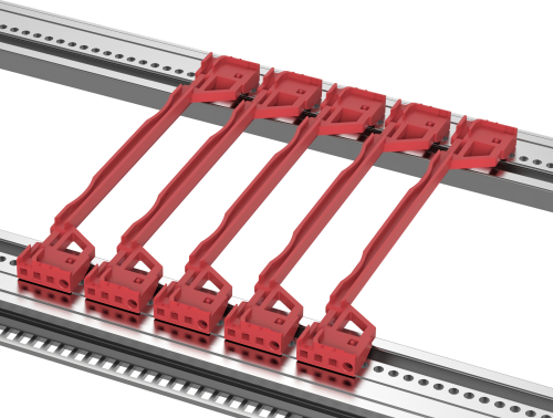
PCB guide rails are small components, but they play an important role in a railway subrack.
A plug-in PCB normally slides between two guide rails. The rails keep the PCB in the correct position and help maintain alignment with the backplane connector.
For railway applications, the guide rail design should consider:
- PCB thickness
- Rail length
- Rail material
- Mounting method
- PCB edge support
- Manufacturing tolerance
- Insertion and extraction force
- Vibration conditions
The guide rail should hold the PCB securely without making insertion and removal unnecessarily difficult.
The connection between the guide rail and the horizontal rail or side structure is equally important. A guide rail with insufficient mechanical retention can move together with the PCB during vibration.
For this reason, PCB guide rail mounting should be treated as part of the overall vibration-resistant subrack design.
3. Keep Backplane and Connector Alignment Stable
Backplane alignment is another critical consideration.
Many railway electronic systems use plug-in boards and multi-pin connectors. When a PCB is inserted, the connector on the PCB must align correctly with the corresponding connector on the backplane.
The mechanical chain can be viewed as:
PCB → Guide Rail → Front Panel → Subrack Structure → Backplane
Movement at any point can affect connector alignment.
Poor alignment can result in:
- Difficult PCB insertion
- Excessive insertion force
- Uneven connector engagement
- Contact problems
- Connector damage
- Intermittent electrical connections
The backplane should therefore be mounted to a sufficiently rigid structure.
The guide rails, horizontal rails, backplane supports, and front panels should be designed together rather than treated as completely independent components.
4. Select the Right Fasteners for Vibration
Fasteners are another potential weak point in a railway subrack.
Typical subrack hardware includes:
- M2.5 screws
- M3 screws
- M4 screws
- Threaded inserts
- Nuts
- Captive screws
- Mounting brackets
Under repeated vibration, a poorly designed joint may gradually lose preload or develop movement.
The designer should consider:
- Fastener size
- Thread engagement
- Joint stiffness
- Material thickness
- Mounting-hole tolerance
- Required assembly torque
- Locking method
For aluminum components, threaded inserts can be useful when a joint needs to be assembled and disassembled repeatedly.
The fastening solution should be selected according to the actual mechanical requirements of the equipment rather than simply choosing the smallest available screw.
5. Secure Heavy Components
A railway subrack may contain components that are significantly heavier than a typical PCB.
Examples include:
- Power supplies
- Transformers
- Large heat sinks
- Fans
- Batteries
- Cooling modules
A heavy component creates greater mechanical loading during acceleration and shock, especially when it is mounted far away from the supporting structure.
A practical design principle is to keep heavy components close to rigid structural members and provide direct mechanical support where possible.
The component’s weight, center of gravity, mounting location, and attachment method should all be considered during the mechanical design.
6. Design Front Panels and Handles as Structural Components
A front panel is not only used for identification or appearance.
In a plug-in railway electronics system, the front panel can also help maintain the position of the PCB assembly.
The panel should be securely attached to the subrack and should not move excessively during vibration.
Handles require similar attention.
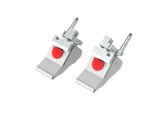
A handle is subjected to mechanical loading when technicians insert or remove a PCB assembly. Its connection to the front panel must therefore be strong enough for repeated operation.
For railway applications, it is useful to consider the complete mechanical path:
Handle → Front Panel → PCB Assembly → Guide Rails → Subrack
Weakness at any connection can become a maintenance or reliability issue.
7. Consider Subrack Resonance
Making a subrack thicker or adding more screws does not necessarily solve every vibration problem.
Every mechanical structure has natural frequencies. If an excitation frequency is close to a natural frequency, the vibration response can increase significantly.
For demanding railway projects, engineers may use finite element analysis (FEA) to examine:
- Natural frequencies
- Mode shapes
- Structural deformation
- Stress concentration
- Mounting-point loads
- Component displacement
Areas that often deserve particular attention include long horizontal rails, large side panels, backplane supports, PCB guide rails, and heavy component mounting points.
This analysis can help identify potential structural problems before physical vibration testing.
8. Consider EMC Grounding During Mechanical Design
Railway electronics often have EMC requirements in addition to mechanical requirements.
The subrack may need reliable electrical contact between different metal components, such as:
- Front panel and horizontal rail
- PCB and chassis
- Backplane and chassis
- Subrack and cabinet
Depending on the design, components such as EMC gaskets, conductive fabric gaskets, grounding clips, and conductive contact areas may be required.
However, EMC components also have mechanical effects.
For example, excessive gasket compression can increase PCB insertion force or interfere with panel assembly.
Therefore, EMC grounding should be considered during the mechanical design rather than added after the chassis has already been completed.
9. Select Materials for Strength, Weight and Environment
Material selection is a balance between mechanical performance and equipment weight.
Aluminum alloys are commonly used in electronic mechanical structures because they offer:
- Low density
- Good machinability
- Good thermal conductivity
- Corrosion resistance
- Useful structural performance
Different components may use different materials.
For example, aluminum can be suitable for panels and structural components, while stainless steel may be selected for specific mounting or EMC applications.
Surface treatment can also affect the final product.
Common options include:
- Anodizing
- Chromate conversion coating
- Conductive surface treatment
- Plating
The appropriate material and surface finish should be selected according to the required mechanical, electrical, environmental, and corrosion performance.
10. Design the Complete Railway Electronics Assembly
One of the most important principles in railway subrack design is to evaluate the complete assembly.
The mechanical behavior of an empty chassis can be very different from the behavior of the finished equipment.
For example, installing multiple PCBs, a backplane, power supply, cooling system, and cables changes:
- Total mass
- Center of gravity
- Natural frequencies
- Load distribution
- Structural stiffness
Therefore, the vibration and shock evaluation should reflect the actual equipment configuration whenever possible.
A useful design model is:
19-inch subrack + PCB + guide rails + backplane + connectors + front panels + fasteners + internal equipment
This gives a more realistic picture of how the equipment will behave during railway operation.
Railway Subrack Vibration Design Checklist
Before finalizing a railway subrack, review the following points:
| Design Area | What to Check |
|---|---|
| Subrack frame | Is the main structure sufficiently rigid? |
| PCB guide rails | Is PCB movement properly controlled? |
| Backplane | Can connector alignment be maintained? |
| Fasteners | Are mechanical joints suitable for repeated vibration? |
| Front panels | Are panels securely retained? |
| Handles | Can they withstand repeated insertion and removal? |
| Heavy components | Are power supplies and other heavy parts adequately supported? |
| Mounting points | Is the load transferred effectively to the cabinet? |
| EMC | Are grounding and shielding interfaces maintained? |
| Materials | Are strength, weight and environmental requirements considered? |
| Resonance | Have natural frequencies been considered? |
| Testing | Does the finished assembly meet the applicable project requirements? |
Common Mistakes in Railway Subrack Design
Several problems can be avoided by considering vibration during the initial mechanical design.
Using a standard subrack without checking the application
A standard 19-inch chassis may have the correct external dimensions but still require changes for railway service.
Ignoring PCB guide rail mounting
The guide rail itself may be strong, but its mounting connection can still allow movement.
Treating the backplane as an independent component
Backplane alignment depends on the relationship between the PCB, guide rails, horizontal rails, and backplane structure.
Testing only the empty chassis
The installed electronics can substantially change the dynamic behavior of the subrack.
Adding EMC components too late
EMC gaskets and grounding clips can affect assembly tolerances and insertion force. They should be included during the mechanical design stage.
What Subrack Parts Are Commonly Used in Railway Electronics?
A railway electronics enclosure may contain many relatively small mechanical components.
Common parts include:
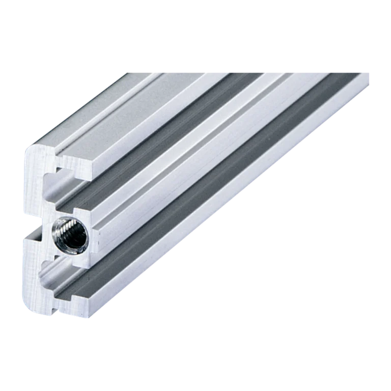
- PCB guide rails
- CPCI guide rails
- Horizontal rails
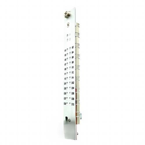
- Front panels
- U-profile panels
- Handles
- Mounting brackets
- Threaded inserts
- Captive screws
- EMC grounding clips
- Conductive gaskets
- Backplane supports
- Custom machined parts
These components may need to match an existing 19-inch subrack or be customized according to a drawing, sample, dimensions, or original part number.
Conclusion
Designing a 19-inch subrack for railway vibration and shock requires attention to the complete mechanical system rather than the chassis frame alone.
Structural stiffness, PCB guide rails, backplane alignment, fastening, heavy components, front panels, EMC grounding, material selection, and resonance all influence the reliability of the finished equipment.
For railway electronics, vibration and shock requirements should be considered from the beginning of the mechanical design process.
If you are replacing a guide rail, horizontal rail, front panel, handle, EMC component, or other subrack mechanical part, the original part number, drawing, dimensions, PCB thickness, or a clear photo can help identify the correct solution.
Looking for a replacement railway subrack component? Send us the original part number, drawing, dimensions, or a photo. We can help identify a suitable replacement or develop a custom alternative for your 19-inch subrack.