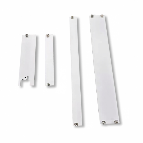
PCB front panels are important mechanical components used in 19-inch subracks, Eurocard systems, industrial computers, telecom equipment, test instruments, railway electronics, and other modular electronic systems.
Unlike a printed circuit board, a PCB front panel is a mechanical panel designed to support, protect, identify, and provide access to electronic modules installed inside a subrack. Depending on the application, it may include PCB mounting features, extractor handles, connector openings, grounding points, ventilation holes, and EMC shielding components.
For equipment manufacturers and purchasing engineers, understanding the PCB front panel manufacturing process is important for controlling dimensions, mechanical strength, surface quality, and compatibility with the complete subrack system.
This article explains the typical manufacturing process, material options, surface treatments, and quality considerations for custom PCB front panels.
What Is a PCB Front Panel?
A PCB front panel is a metal or engineered component mounted at the front of a PCB module or electronic plug-in unit.
In a typical 19-inch subrack, the front panel works together with components such as:
- PCB guide rails
- PCB extractor handles
- Front panel handles
- Mounting brackets
- Horizontal rails
- EMC gaskets
- Grounding clips
- Backplane and connectors
The front panel can provide mechanical protection while also helping engineers identify and access individual electronic modules.
For Eurocard and 19-inch subrack applications, panel dimensions and mounting positions should be designed according to the requirements of the overall enclosure system and applicable standards such as IEC 60297.
PCB Front Panel Manufacturing Process
A typical custom PCB front panel manufacturing process includes:
Material Selection → Cutting → CNC Machining or Stamping → Bending → Threading/Fastening → Deburring → Surface Treatment → Marking → Assembly → Inspection
The exact process depends on the material, design complexity, production volume, and required tolerance.
1. Material Selection
Material selection is the first step in manufacturing a PCB front panel.
Common materials include aluminum, stainless steel, SPCC, and SECC.
Aluminum
Aluminum is widely used when low weight, corrosion resistance, and good machinability are important.
Common aluminum alloys include:
- 5052
- 6061
- 6061-T6
- 6063
6061-T6 aluminum is particularly suitable for CNC-machined components where higher mechanical strength is required.
5052 aluminum is easier to form and is often selected for sheet-metal front panels requiring bending.
Steel
SPCC and SECC steel are common choices for cost-sensitive applications.
Steel panels generally provide good rigidity and dimensional stability and can be powder coated or painted in different colors.
Stainless Steel
Stainless steel may be selected for applications requiring higher corrosion resistance or special environmental durability.
The material should ultimately be selected according to the mechanical, environmental, electrical, and cosmetic requirements of the equipment.
2. Sheet Metal Cutting
After material selection, the raw sheet is cut according to the engineering drawing.
Depending on the production quantity and design, manufacturers may use:
- Laser cutting
- CNC punching
- Shearing
- Stamping
Laser cutting is particularly useful for prototypes and small-to-medium production runs because it does not require an expensive stamping die.
For high-volume production, stamping can provide faster cycle times and lower unit costs after the tooling investment has been amortized.
3. CNC Machining
CNC machining is commonly used when a PCB front panel requires precise holes, slots, connector openings, countersinks, or complex geometries.
Typical CNC operations include:
- Drilling
- Milling
- Countersinking
- Slot machining
- Thread tapping
- Edge machining
For example, a custom front panel may require M2.5, M3, or M4 mounting holes for handles, brackets, or other subrack accessories.
Connector openings can also be CNC machined according to the required connector dimensions.
For prototypes and custom components, CNC machining provides flexibility without requiring a dedicated stamping die.
4. Stamping and Punching
Stamping is another important manufacturing method for sheet-metal PCB front panels.
It is particularly suitable for large-volume production.
A stamping die can be designed to produce:
- Mounting holes
- Ventilation openings
- Slots
- Embossed features
- Cutouts
- Positioning features
The major advantage of stamping is production efficiency.
However, tooling costs should be considered when comparing stamping with laser cutting or CNC machining.
For low-volume projects, laser cutting or CNC machining may be more economical. For high-volume projects, stamping can significantly reduce the cost per piece.
5. Bending and Forming
Some PCB front panels are not flat plates.
They may include folded edges, reinforcement structures, mounting flanges, or L-shaped and U-shaped sections.
These features can be produced using a CNC press brake or other sheet-metal forming equipment.
Bending can improve the rigidity of a thin panel without significantly increasing its weight.
The engineering drawing should specify important bending parameters such as:
- Bend angle
- Bend radius
- Material thickness
- Bend direction
- Overall dimensions
- Flatness requirements
These factors are particularly important when the panel must fit precisely inside a 19-inch subrack.
6. Threading and Fastening
PCB front panels often require threaded holes or fastening components.
Common solutions include:
- CNC tapped holes
- Rivet nuts
- Press-fit nuts
- PEM nuts
- Captive nuts
- Rivets
For thin sheet metal, press-fit nuts or rivet nuts can provide more reliable threads than directly tapping the sheet.
The appropriate fastening method depends on the panel thickness and the expected number of assembly and disassembly cycles.
7. Deburring and Edge Treatment
After laser cutting, punching, or CNC machining, sharp edges and burrs may remain on the panel.
Deburring is therefore an important manufacturing step.
Typical processes include:
- Manual deburring
- Mechanical deburring
- Brushing
- Tumbling
- Edge rounding
Proper edge treatment improves operator safety and helps prevent damage to PCBs, cables, connectors, and other electronic components during assembly.
8. Surface Treatment
Surface treatment affects the appearance, corrosion resistance, durability, and sometimes electrical performance of a PCB front panel.
The appropriate process depends on the material.
Anodizing
Anodizing is widely used for aluminum components.
Common options include:
- Natural anodizing
- Black anodizing
- Silver anodizing
Anodizing provides a durable oxide layer and can produce a clean, professional appearance.
Powder Coating
Powder coating is commonly used for steel and aluminum panels.
It allows manufacturers to achieve various colors according to requirements such as:
- RAL7035
- RAL9005
- RAL3000
Powder coating is particularly common for industrial equipment and electronic enclosures.
Chromate Conversion Coating
Chromate conversion coating may be used on aluminum when corrosion resistance and electrical conductivity are both important.
This treatment can be useful for components requiring electrical bonding or EMC grounding.
However, the required coating specification should be clearly defined because surface treatment can affect electrical contact between mating components.
9. Screen Printing and Laser Marking
A professional PCB front panel often requires identification markings.
Typical markings include:
- Product model
- Connector labels
- Port numbers
- Company logo
- Warning symbols
- Functional descriptions
- Arrow indicators
Two common methods are screen printing and laser marking.
Screen printing is suitable for clear and economical graphics.
Laser marking provides high precision and good durability and is often used when permanent identification is required.
10. Assembly
After machining and surface treatment, the panel can be assembled with other subrack components.
Depending on the design, this may include:
- PCB extractor handles
- PCB guide rails
- Mounting brackets
- EMC gaskets
- Grounding clips
- Screws
- Captive hardware
- Connector accessories
The final assembly should be checked to ensure that all components fit correctly and that the front panel can be installed and removed smoothly from the subrack.
PCB Front Panel Quality Inspection
Quality control is essential because even a small dimensional error can affect the installation of an electronic module.
Important inspection items include:
Dimensional Accuracy
Check:
- Overall length and height
- Hole diameter
- Hole position
- Slot dimensions
- Connector openings
- Bend dimensions
- Panel thickness
Flatness
Excessive deformation can make it difficult to install the panel or align it with neighboring components.
Surface Quality
Inspect for:
- Scratches
- Dents
- Burrs
- Coating defects
- Color variation
- Oxidation marks
Thread Quality
Threaded holes should be checked using appropriate gauges to ensure correct screw engagement.
Assembly Compatibility
The completed panel should be tested with the corresponding:
PCB + guide rail + extractor handle + subrack
rather than being inspected only as an individual component.
This helps identify assembly problems that may not be obvious during dimensional inspection.
How to Choose the Right PCB Front Panel Manufacturing Process
The best manufacturing process depends on several factors.
| Requirement | Recommended Process |
|---|---|
| Prototype | CNC / Laser Cutting |
| Small Batch | CNC / Laser Cutting |
| Large Volume | Stamping |
| Complex Machined Features | CNC Machining |
| Folded Structure | CNC Bending |
| Lightweight Panel | Aluminum |
| High Rigidity | Steel / 6061-T6 |
| Premium Aluminum Finish | Anodizing |
| Industrial Color | Powder Coating |
| Permanent Marking | Laser Marking |
| Electrical Bonding | Conductive Surface Treatment |
There is no single manufacturing process suitable for every PCB front panel.
A good supplier should evaluate the drawing, material, tolerance, production quantity, surface finish, and assembly requirements before selecting the manufacturing process.
Custom PCB Front Panel Manufacturing
For special electronic equipment, standard panels may not meet the required dimensions or mounting configuration.
Custom PCB front panels can be manufactured according to:
- 2D engineering drawings
- 3D CAD files
- Original part numbers
- Samples
- Dimensions
- Product photographs
Custom manufacturing can include material selection, CNC machining, stamping, bending, surface treatment, printing, and final assembly.
This is particularly useful when an original component has been discontinued or when an OEM needs a replacement part compatible with an existing subrack.
PCB Front Panels for 19-Inch Subracks
For 19-inch subrack applications, mechanical compatibility is critical.
The panel should be designed together with the complete system, including the rack, guide rails, PCB, backplane, connectors, handles, and mounting hardware.
Important considerations include:
- 19-inch rack compatibility
- 3U / 6U height
- PCB dimensions
- PCB guide rail position
- Connector alignment
- Front panel mounting
- EMC requirements
- Grounding
- Thermal management
- Serviceability
A correctly designed front panel should allow the electronic module to slide into the subrack smoothly while maintaining accurate connector alignment.
Conclusion
The manufacturing of a PCB front panel involves much more than simply cutting a piece of metal.
A typical production process may include material selection, laser cutting or stamping, CNC machining, bending, threading, deburring, surface treatment, marking, assembly, and final inspection.
For 19-inch subrack and Eurocard applications, dimensional accuracy and compatibility with the complete mechanical system are especially important.
Choosing the right manufacturing process also depends on production volume, material, tolerance, surface finish, and application requirements.
If you need a custom PCB front panel for a 19-inch subrack, providing a drawing, sample, dimensions, or original part number allows the manufacturer to evaluate the design and recommend an appropriate production method.
Looking for a custom PCB front panel supplier?
Send us your drawing, dimensions, original part number, or product photo. YiHui can help evaluate the design and provide a suitable manufacturing solution for your 19-inch subrack application.