Designing a front panel for a 19-inch Eurocard system requires more than selecting a standard 3U or 6U panel size. The panel must match the mechanical dimensions of the subrack, mounting-hole positions, plug-in unit, PCB, guide rails, connectors, and other components.
For engineers designing or replacing Eurocard front panels, IEC 60297 provides the basic mechanical framework for 482.6 mm (19-inch) systems.
In particular, IEC 60297-3-100 defines the basic dimensions of front panels, subracks, chassis, racks, and cabinets. IEC 60297-3-101 then provides more detailed mechanical requirements for subracks and plug-in units.
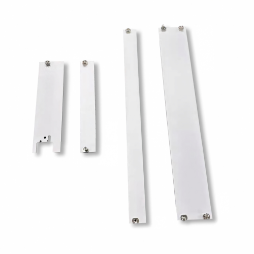
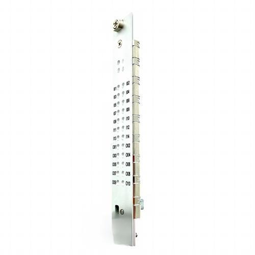
This article explains how to design a 3U or 6U Eurocard front panel according to IEC 60297, including panel height, width, mounting holes, horizontal pitch, panel thickness, and manufacturing considerations.
1. Start With the IEC 60297 Mechanical System
IEC 60297 is based on the 482.6 mm (19-inch) equipment system.
The basic height unit is:
1U = 44.45 mm
Therefore:
- 1U = 44.45 mm
- 2U = 88.90 mm
- 3U = 133.35 mm
- 4U = 177.80 mm
- 5U = 222.25 mm
- 6U = 266.70 mm
These are nominal height increments. The actual front-panel height defined by IEC 60297-3-100 includes the required clearance within the U-unit envelope.
For example, the standard specifies:
| Front Panel | Nominal Height | Actual Panel Height |
|---|---|---|
| 1U | 44.45 mm | 43.65 ± 0.4 mm |
| 2U | 88.90 mm | 88.10 ± 0.4 mm |
| 3U | 133.35 mm | 132.55 ± 0.4 mm |
| 4U | 177.80 mm | 177.00 ± 0.4 mm |
| 5U | 222.25 mm | 221.45 ± 0.4 mm |
| 6U | 266.70 mm | 265.90 ± 0.4 mm |
The tolerances are non-cumulative.
This distinction is important when producing a 3U or 6U front panel. The nominal U height should not simply be used as the finished panel height.
2. Define the Front Panel Width
The nominal width of the 19-inch front-panel system is:
482.6 ± 0.4 mm
However, this does not mean that every plug-in front panel is 482.6 mm wide.
The 482.6 mm dimension represents the overall 19-inch equipment interface. Individual Eurocard plug-in units occupy only a portion of the available horizontal space.
For modular plug-in systems, the horizontal position is based on a pitch of:
5.08 mm
This is commonly referred to as 1 HP in Eurocard and subrack systems.
Therefore:
1 HP = 5.08 mm
The number of horizontal pitches determines the available width for an individual plug-in unit.
For example:
n HP × 5.08 mm = nominal horizontal pitch width
When designing a replacement front panel, however, the final panel width should be derived from the actual plug-in-unit and subrack interface rather than simply multiplying HP values.
IEC 60297-3-101 specifies the relevant plug-in-unit dimensions and 5.08 mm horizontal pitch used for the mechanical interface.
3. Design the 3U Eurocard Front Panel
The 3U configuration is one of the most widely used formats for Eurocard-based systems.
According to IEC 60297-3-100:
3U nominal height = 133.35 mm
3U front-panel height = 132.55 ±0.4 mm
The standard gives the corresponding mounting-hole geometry and reference dimensions for the 3U panel.
A typical 3U front-panel design should therefore start with:
- 132.55 ±0.4 mm panel height
- IEC 60297 mounting-hole arrangement
- Appropriate horizontal module width
- Defined panel thickness
- PCB extractor or handle mounting
- Connector cutouts where required
- Optional EMC grounding interface
The exact width depends on the module’s horizontal pitch.
4. Design the 6U Eurocard Front Panel
For a 6U system:
6U nominal height = 266.70 mm
6U front-panel height = 265.90 ±0.4 mm
IEC 60297-3-100 allows different mounting-hole arrangements for 6U front panels. The standard specifically provides two possible hole-spacing configurations for 6U panels.
This is important when replacing an existing 6U front panel.
A replacement panel should therefore be checked against:
- Overall panel height
- Mounting-hole positions
- Hole diameter
- Hole spacing
- Panel width
- Horizontal pitch
- Extractor position
- Connector openings
- Adjacent module clearance
A panel with the correct 6U height can still be incompatible if its mounting-hole arrangement does not match the subrack.
5. Follow the IEC 60297 Mounting-Hole Geometry
Mounting holes are one of the most important features of an IEC 60297 front panel.
IEC 60297-3-100 defines the basic mounting-hole geometry and provides two mounting-hole types. The standard also allows different mounting-hole arrangements depending on panel height and mechanical requirements.
The standard dimensions shown for the front-panel mounting interface include values such as:
- 482.6 ±0.4 mm overall reference width
- 6.8 mm mounting-hole dimension
- 10.3 ±0.4 mm
- 13.5 ±0.4 mm
- 14.7 +0.5/−0 mm
- Height-specific H1, H2 and H3 dimensions
The exact dimensions and their reference locations should be taken directly from the applicable IEC 60297 drawing rather than recreated from an approximate measurement.
For production drawings, it is better to establish a clear datum system and dimension all critical holes from the same reference rather than dimensioning holes cumulatively.
6. Do Not Assume IEC 60297 Defines Panel Thickness
One common design mistake is to state that IEC 60297 requires a specific front-panel thickness.
It does not.
IEC 60297-3-100 explicitly states that front-panel thickness is not defined by the standard.
This means the designer can select the thickness according to:
- Panel material
- Mechanical load
- Required rigidity
- Connector weight
- Extractor design
- EMC requirements
- Manufacturing process
- Surface treatment
- Weight limitations
For example, an aluminum panel may use a different thickness from a steel panel even when both are designed for the same 3U Eurocard system.
The correct approach is therefore:
IEC 60297 defines the interface → engineering requirements define the panel thickness.
7. Match the Front Panel With the PCB
A Eurocard front panel should not be designed independently from the PCB.
IEC 60297-3-101 describes a board-type plug-in unit as a combination of the printed board, front panel, fixing parts, and connector, with dimensions designed to ensure compatibility with the subrack.
The mechanical chain should therefore be checked as one system:
Front Panel → PCB → Guide Rail → Connector → Backplane
The PCB dimensions, connector position, guide-rail location, and front-panel mounting geometry must all work together.
Important PCB-related parameters include:
- PCB height
- PCB thickness
- PCB depth
- Connector position
- Guide-rail position
- Front-panel mounting position
- Extractor mounting location
A front panel may meet the basic IEC 60297 dimensions but still fail in a real assembly if the PCB and connector geometry are incorrect.
8. Use 5.08 mm Horizontal Pitch Correctly
The 5.08 mm pitch is fundamental to Eurocard plug-in-unit design.
IEC 60297-3-101 uses a 5.08 mm horizontal pitch for the modular subrack interface.
This pitch determines the position of:
- PCB slots
- Guide rails
- Plug-in units
- Front panels
- Connectors
- Backplane positions
For example:
1 pitch = 5.08 mm
10 pitches = 50.8 mm
20 pitches = 101.6 mm
When creating a CAD model, it is recommended to establish the pitch grid first and then position the front panel, PCB, guide rail, and connector relative to this grid.
This approach reduces cumulative dimensional errors and simplifies interchangeability.
9. Design the Front Panel for PCB Extractors
A Eurocard front panel commonly includes a PCB extractor or handle.
The extractor is not simply an accessory attached after the panel has been designed. Its mounting location must be incorporated into the front-panel design.
Check:
- Extractor mounting-hole position
- Screw or rivet interface
- Lever travel
- Adjacent-slot clearance
- PCB position
- Connector engagement
- Panel thickness
- Handle orientation
The extractor must provide enough mechanical leverage to disengage the PCB connector without interfering with neighboring modules.
For this reason, the front panel, PCB extractor, guide rail, and connector should be evaluated as a complete plug-in unit.
10. Add Connector Cutouts According to the PCB
Many Eurocard front panels require openings for connectors and indicators.
Common openings include:
- D-sub connectors
- RJ45 connectors
- Fiber-optic connectors
- USB connectors
- Circular connectors
- LEDs
- Displays
- Push buttons
- Switches
The opening dimensions should be derived from the actual connector and PCB layout.
Do not position the opening based only on the external appearance of the connector.
Instead, establish the relationship:
PCB datum → connector center → front-panel opening → panel datum
This method improves assembly accuracy and reduces the risk of connector misalignment.
11. Consider EMC/EMI Requirements
IEC 60297-based subracks can also incorporate electromagnetic shielding provisions. IEC 60297-3-101 identifies EMC shielding as an optional feature of subrack and plug-in-unit designs.
If the front panel is part of an EMC shielding system, consider:
- Conductive panel material
- EMC gasket
- Conductive fabric gasket
- Metal mesh gasket
- Grounding clips
- Conductive springs
- Electrical contact area
- Paint removal at grounding points
For painted aluminum or steel panels, the coating should not unintentionally isolate the panel from the required grounding path.
Therefore, EMC design should be considered during the mechanical drawing stage rather than added after production.
12. Select Material and Surface Treatment
IEC 60297 defines the mechanical interface but does not force a single material for front panels.
Common choices include:
Aluminum
Advantages include:
- Low weight
- Good corrosion resistance
- Easy CNC machining
- Good thermal conductivity
- Suitable for anodizing
Common alloys include 6061 and 5052, depending on the manufacturing process and mechanical requirements.
Steel
Steel can provide:
- High rigidity
- Good mechanical durability
- Cost-effective sheet-metal manufacturing
- Compatibility with industrial powder coating
Materials such as SPCC or SECC can be considered depending on the application.
Surface Finishing
Possible finishes include:
- Anodizing
- Chemical conversion coating
- Powder coating
- Painting
- Plating
The final finish should be selected according to appearance, corrosion resistance, electrical conductivity, and EMC requirements.
13. IEC 60297 Front Panel Design Checklist
Before releasing a front-panel drawing, use the following checklist:
| Design Item | Requirement |
|---|---|
| Equipment format | 19-inch / 482.6 mm |
| Height unit | 1U = 44.45 mm |
| 3U nominal height | 133.35 mm |
| 3U actual panel height | 132.55 ±0.4 mm |
| 6U nominal height | 266.70 mm |
| 6U actual panel height | 265.90 ±0.4 mm |
| Horizontal pitch | 5.08 mm |
| Mounting holes | IEC 60297 geometry |
| Panel thickness | Engineering-defined |
| PCB interface | Check with IEC 60297-3-101 |
| Guide rail | Check position |
| Extractor | Check mounting and clearance |
| Connector openings | Match PCB |
| EMC | Add if required |
| Material | Aluminum / steel / other |
| Surface treatment | Application-dependent |
The basic height and mounting dimensions above are based on IEC 60297-3-100, while the plug-in-unit and subrack interface should be checked against IEC 60297-3-101.
14. How to Design a Custom IEC 60297 Front Panel
For a new project, the recommended design process is:
Step 1 — Define the system
Determine:
- 19-inch system
- 3U or 6U
- Number of HP
- PCB dimensions
- Subrack depth
Step 2 — Establish the IEC 60297 datum
Use the applicable IEC 60297 front-panel dimensions as the master reference.
Step 3 — Create the pitch grid
Establish the 5.08 mm horizontal pitch for the plug-in unit and related components.
Step 4 — Position the mounting holes
Use the applicable IEC 60297 mounting-hole arrangement.
Step 5 — Add PCB and connector geometry
Position the PCB, guide rail, connector, and backplane interface.
Step 6 — Add extractor or handle
Verify the mounting interface and operating clearance.
Step 7 — Add cutouts
Add connector, LED, switch, display, and ventilation openings.
Step 8 — Define material and thickness
Select the material and thickness based on the mechanical requirements.
Step 9 — Define EMC requirements
Add grounding areas, conductive gaskets, or other shielding provisions if necessary.
Step 10 — Release the manufacturing drawing
Specify:
- Dimensions
- Tolerances
- Material
- Surface treatment
- Hole specifications
- Deburring requirements
- Marking requirements
- Inspection requirements
Conclusion
A reliable IEC 60297 front panel design starts with the standard mechanical interface and then adapts the panel to the actual Eurocard plug-in unit.
For a 3U panel, the nominal height is 133.35 mm, while the specified panel height is 132.55 ±0.4 mm. For a 6U panel, the nominal height is 266.70 mm, while the specified panel height is 265.90 ±0.4 mm. The 19-inch system uses a nominal width of 482.6 mm, and Eurocard plug-in-unit positioning is based on a 5.08 mm horizontal pitch.
However, IEC 60297 does not define every aspect of a finished front panel. In particular, panel thickness, material, connector cutouts, surface finish, and extractor selection must be determined according to the application and mechanical design requirements.
For replacement or custom front panels, providing the original drawing, part number, dimensions, or a photo can help manufacturers determine the correct IEC 60297 interface and identify differences between the original component and the replacement.
Need a Custom IEC 60297 Front Panel?
At Subrack Parts, we support custom front panels and related 19-inch subrack components, including PCB extractors, guide rails, mounting hardware, EMC/EMI grounding components, and other Eurocard accessories.
Send us your original part number, CAD drawing, dimensions, or product photo. We can help evaluate the mechanical interface and develop a suitable replacement or custom front panel for your 19-inch Eurocard system.